This thread has been locked.

If you have a related question, please click the "Ask a related question" button in the top right corner. The newly created question will be automatically linked to this question.

TPA3255EVM: Whether TPA3255EVM are suitable for diriving inductive coil

Part Number: TPA3255EVM
Other Parts Discussed in Thread: TPA3255

Hi, guys

Sorry to bother, I have searched some of the posts about using speaker amplifier beyond audio application, but I can't find solutions to mine.

My application is to drive inductive coil load (multiple turns of wire). 

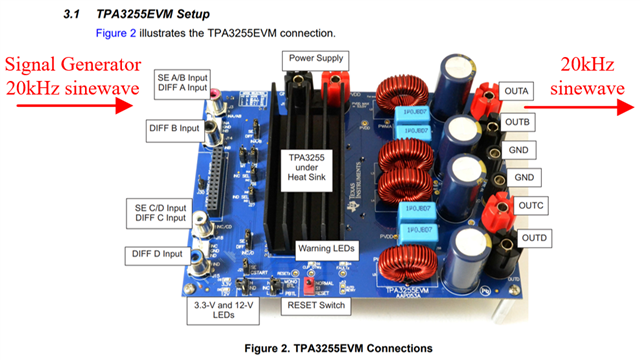
Input signal of PA: 20kHz sinewave, voltage signal

Wanted output signal to drive the load: 20kHz sinewave, 0~2A (adjustable step, e.g. 0.1A increment)

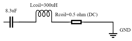
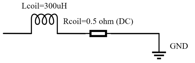
Load: Classical series resonanance: L of the coil =300uH, series C = 8.3uF, DC resistance of coil is 0.5 ohm. The load is resonant at 20kHz, so the L and C are cancelled out. Only remain DC resistance of coil.

My question is:

Q1: Since I not familiar with audio amplifier design, so I want to buy the evaluation board directly. Can I just connect the signal generator and feed the 20kHz sinewave to this evaluation board?

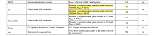
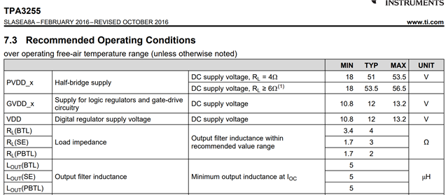
Q2: And to match the recommened load 2 ohm~4ohm load required by TPA 3255 (screen shot below), I connect a roughly 3.5 ohm power resistor. Is it OK? 

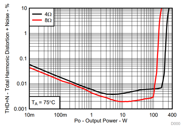
Q3: Since I also want to change the current in the coil in steps, does TPA3255EVM support adjusting the current by adjusting the output power? (e.g evaluation board output 8W corresponds to 1A, 9.68W corresponds to 1.1A. 18W corresponds to 1.5A, 32W corresponds to 2A). Or any methond that I can adjust the current?

Q4: I have seen in other posts that we need to choose LC filter, but because my load itself is a inductive, so do we need LC filter again? Beacause I think LC filter will change the resonant frequency.

Q5: If this evaluation board is suitable for my application. Any other things I need to notice?

Q6: Another question is can speaker amplifier directly drive the inductive coil? Will it cause unstable or something? I know for capacative load we need to do compensation network, but for inductive load? It seems that 300uH at 20kHz, its impedance is Z=2×pi×20kHz×300uH = 37.7 ohm, so is flowing 0~2A OK?

Best Regards

Grant Ward

  • Hi Grant.

    About your questions.

    Q1: Yes, you can use signal generator to generate input signal.

    Q2: Yes, it's ok. You need to make sure the current does not trigger the OC value as below.

    Q3: You can adjust the amplitude of the input signal to increase the output voltage, thereby increasing the output current (with the same load).

    Q4: The function of LC filter is to meet EMC spec, you can remove LC in your application.

    Q5: I think it's okay, you should make sure that it will not trigger OC when your LC load is resonance(If you only output 20kHz signal, only need to guarantee 20k and startup).

    Q6: Yes, AMP can drive inductive coil. Actually, Speakers model is consistent of inductor and resistance. 

    Because of fixed load, so the current flowing through the load is related to the output voltage. 

    TPA3255 max PVDD is 53.5V, so the peak current is 53.5/37.7=1.42A(Considering the RDSON of the internal MOS, it will actually be smaller).


    Hope these reply can help you.

    BR.

    Wei Qiu.

  • Thanks Qiu!

    Thanks for your detailed reply. I have fully understood. And Now I am confident to use this board

    But still two little question 

    Q1: Since audio amplifier is optimized for speaker (since datasheet mostly list performace at load of 4 ohm/8ohm), so to obtain best THD+N performance, may I guess: is it "using sereis L+C+R resonance and add a series resistance to make total load 4/8 ohm, and flow with roughly 1~2A"  better than "directly driving inductice load and flow 1~2A"?

    Q2: Another is about driving resonance LCR or directly driving coil, when it is shuntdown,  the inductive coil will have huge kick-back that  current flows back to the board output port. Below is previously what I have seen about preventing inductive coil kick back, I guess use diode in this figure may protect. But I didn't see diode in tpa3255evm's output. So can I safely just shunt down the power?

    Best Regards

    Grant Ward

  • Hi Grant.

    I'm glad my response can help you.

    About your questions:

    Q1: Actually 4Ohm/8Ohm is a typical value of speakers DCR value. You can look for the impedance curve of a speaker, which also has a low-frequency resonance point and is inductive at high frequencies. So it is not that the closer the impedance is to the typical value, the better. Our power amplifier feeds the two terminals of Output _P and Output _N, so generally speaking, it will have better THD.

    In addition, the output of Output _P and Output _N is a waveform with a high-frequency switching frequency containing input audio components, and you need to pay attention to whether it affects your load. In audio applications, only the 20-20k component is concerned, so the high-frequency switching frequency can be ignored.

    Q2: According to your description, it is indeed possible. We have no relevant research here, and it is recommended to actually use the EVM board to test it.

    BR.

    Wei Qiu.

  • Thanks Wei Qiu

    Thank you very much for your detailed answer. Now I have fully understood the problems that this evaluation board may encounter in my application and how to solve it. Thank you again, wish you success in your work

    Best Regards

    Grant Ward