This thread has been locked.

If you have a related question, please click the "Ask a related question" button in the top right corner. The newly created question will be automatically linked to this question.

TLV320AIC3268: CODEC ADC Count vs Input Voltage & Full Scale Range Issue

Part Number: TLV320AIC3268

Hi,

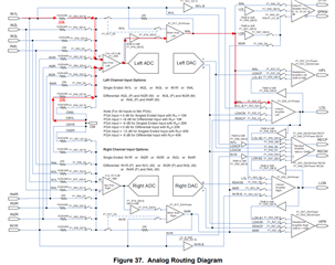
We are using TI CODEC part TLV320AIC3268IRGCT in our design. While CODEC validation we have seen that the ADC output count is less compared to actual input sinusoidal signal amplitude.

We are using a VOGAD IC prior to CODEC input so that a voltage of around 1Vpp to 1.2Vpp will be always available at CODEC ADC input. ADC input full scale range should support 0.5Vrms or 1.414Vpp.

If we are giving an input amplitude of 1Vpp ADC output is only around +-500 counts in amplitude which is significantly less than the input amplitude. We are getting +-500 counts with 0dB PGA gain at ADC front end. If we are increasing PGA gain to +6dB count is increasing. If PGA gain is increased to +12dB ADC count is reaching around +-2500 and is saturation. But ADC should saturate at full-scale range count of around +-32000.

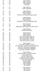
Below is the CODEC register configuration for review.

Note: CODEC DAC is independently validated by output sinusoidal signal using FPGA DDS. We are facing issue with ADC performance.

Regards

Hafiz Haja

  • Hello Hafiz,

    Thank you for reaching out.

    A few questions for clarification:

    • When you say "counts" are you referring to the digital bit value?
    • Where are you measuring ADC output (is this the digital value off of the I2S bus)?
    • Is the input a single analog ended microphone or differential? and what pins is the mic connected to?

    Best,
    Andrew

  • Hello Andrew Jackiw,

    1. When you say "counts" are you referring to the digital bit value?

    Reply : Yes. We are referring ADC digital output bus value as count in the above query.

    2. Where are you measuring ADC output (is this the digital value off of the I2S bus)?

    Reply : You're right. We are measuring the digital value of the ADC output at the ASI (Mono PCM) interfaced with FPGA.

    3. Is the input a single analog ended microphone or differential? and what pins is the mic connected to?

    Reply : It is single ended analog input to IN1L ADC pin. Other ADC input pins are connected to GND via 0.47uF as recommended.

    We don't see any issue related ASI with FPGA. We could see proper sinusoidal output in the ADC digital data bus.

    We also did loop-back between ADC digitized samples output to DAC digital samples input (ASI1_DataOutput - ASI1_DataInput). We see 30dB amplitude drop at DAC output with the loop-back configuration.

    Our ADC channel path overall gain is 0dB. For 1Vpp input at IN1L, ADC digital output count is only around +/- 500. Count becomes +/- 1000 if we increasing the PGA gain to 6dB. And the ADC digital output count becomes +/-2000 if we increasing the PGA gain to 12dB. ADC digital output becomes saturated if we further increasing the PGA gain. But the ADC digital output bus count is only +/-2000. ADC digital output bus value should be around +/-32768 when the ADC is saturated. Kindly look in to the configuration and let us know if we are missing anything in the CODEC configuration.

    We are awaiting for your reply.

    Regards

    Loganathan N

  • Hello Loganathan, 

    There is nothing that sticks out as an issue with your register configuration. What is the format and word length of data that the FPGA is using to decode the counts? By default, the codec is 16-bit I2S. Sometimes, this can be a result of a data width mismatch between the codec and controller. 

    Attenuation can also be the result of the input selection (Rin) (see 8.3.2.2 ADC Gain Setting and table 7). 

    Best,
    Andrew

  • Hello Andrew,

    Thanks for your response. CODEC ASI1, Audio Bus Format has been configured in Mono PCM format with 16bit data length. FPGA is slave in this ASI1 interface (WCLK and BCLK is generated from the CODEC). We don't see any issue related to the ASI. Because DAC output is validated by providing full scale input to the ASI from the FPGA (Generating tone using DDS).

    Attenuation can also be the result of the input selection (Rin) (see 8.3.2.2 ADC Gain Setting and table 7). 

    Reply : As per the above configuration, Rin value is configured as 20kohm for both IN1L and CM1L. With this series resistor value, ADC output is getting saturating if the PGA gain is more than 12dB (Where the digital output bus count value is only around +/-2000).

    If the Rin value is configured to 10kohm for both IN1L and CM1L. With this series resistor value, ADC output is getting saturating if the PGA gain is more than 6dB (Where the digital output bus count value is still only around +/-2000, because overall gain is same compared to Rin as 20Kohm).

    Regards

    Loganathan N

  • Hello Loganathan,

    I don't see any issues with the configuration above. I have a few methods to try and identify the issue:

    1. Bypass the ADC. This will help to check if there is any attenuation happening in the device if no gain is applied (0dB) then the input should match the output and we can make sure the analog value at the input of the ADC is the expected value.

    2. It is hard to diagnose this issue since I cannot tell what counts is refenced to or how the FPGA is handling this data. Is there any lab equipment that can be used to decode the ADC data? We use the Audio Precision (APx555) to accomplish this. 
      1. Essentially my questions here is: How is 'counts' derived/measured?

    Best,
    Andrew