Hi Dear,
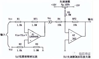
As shown in the following figure, without changing the drift of the operational amplifier, the offset can be zeroed in the circuit. Does TI have such a mature design, and how to choose A1 and A2 operational amplifiers?

This thread has been locked.
If you have a related question, please click the "Ask a related question" button in the top right corner. The newly created question will be automatically linked to this question.
Hi Dear,
As shown in the following figure, without changing the drift of the operational amplifier, the offset can be zeroed in the circuit. Does TI have such a mature design, and how to choose A1 and A2 operational amplifiers?

Hi Anna,
We offer a portfolio of high-precision, low offset, low drift amplifiers. The op-amp selection / circuit would depend on the application requirements.
Can you kindly let me know:
Voltage supply requirement:
- Is this a ±15V bipolar supply connected to the Rp pot on figure above? or what are the supply voltages available in the system?
Input signal requirements:
- What is the differential input signal max amplitude?
- What is the DC input common mode voltage or average voltage of the Vi1 and Vi2 inputs: (Vi1+Vi2)/2
- What is the max input frequency or bandwidth required on the overall circuit?
Output requirements:
- What is the overall gain, is it 1000V/V as shown above?
- What is the maximum output amplitude required?
- What circuit or load is connected at the output of amplifier A2?
General requirements:
- Is the zero adjustment intended to eliminate the op-amp intrinsic offset? or intended to eliminate an external offset?
If the zero offset adjustment is primarily intended to eliminate a sensor or external offset, what offset adjustment ± range do you require?
- Do you have any strict gain error accuracy/drift, offset accuracy/drift or noise requirements? Please note, the percent gain error and gain error drift will be primarily a function of the resistor component tolerance and resistor drift...
Thank you and Regards,
Luis
Hi Luis,
The output terminal is connected to a PLC or butterfly valve, with an output range of -1 to 11V.And the transmission distance should be 15 meters.
It is to modulate the PWM output of the microcontroller into the required voltage signal through an operational amplifier.
The customer wants to adjust the external offset and the zero range is expected to be around ±0.5V or ±1V
Hi Anna,
Do you know what the frequency of the PWM signal is? Without knowing the specific signal bandwidth requirements is difficult to provide a detailed answer.
On the output stage, since you are driving 15m of cable, do you have an estimate of the maximum load capacitance?
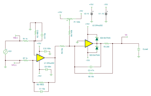
One possibility may be to configure the second stage amplifier on the dual-feedback configuration.
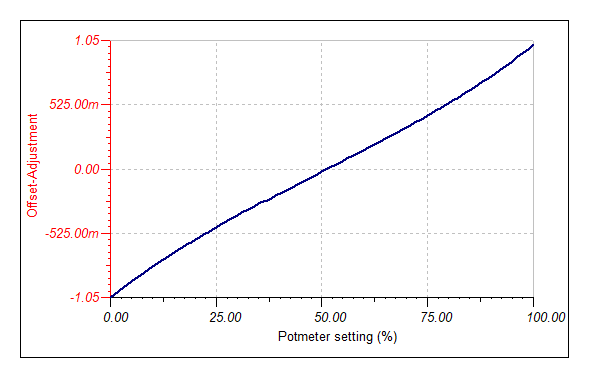
The output stage example below should be able to handle capacitive loads up to 47nF and has a zero adjustment range of ±1V:


Thank you and Regards,
Luis