


Hi,
I am posting this on behalf of my team working on a project that involves the recording of ultrasonic sounds using a mems microphone (SPH0641LU4H-1), and PDM to I2S translation of the audio output with the PCM3180. I read in the I2S data on a raspberry pi 0 2 W running Ubuntu server. I believe that the microphone is successfully outputting PDM data, and I have verified the PCMD3180 connections based on the applications diagram in the data sheet. I seem to be recording garbage data from the microphone, and am not sure how to proceed.
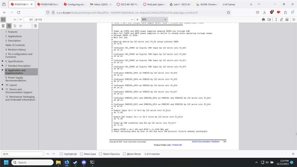
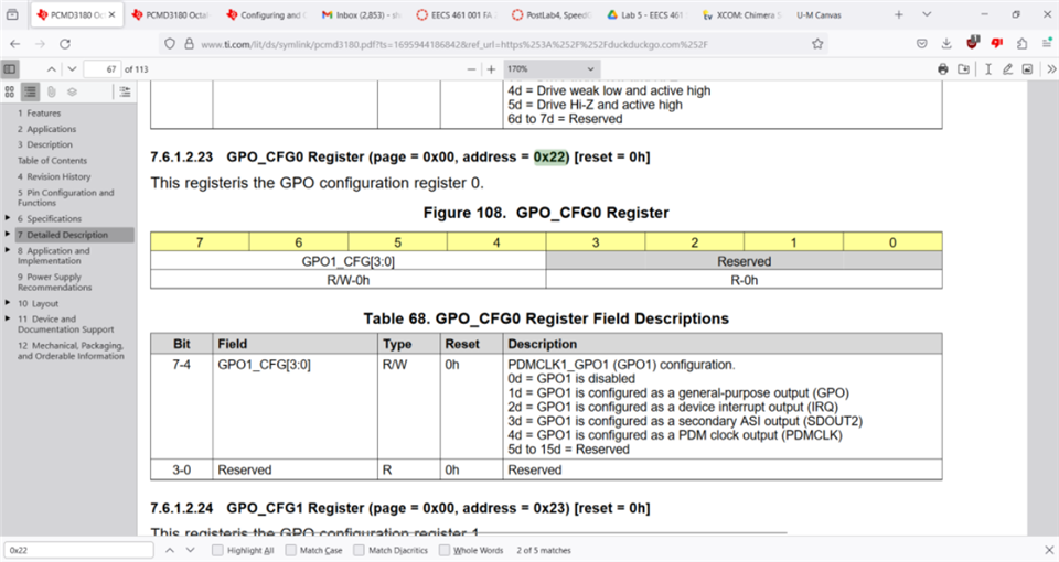
My theory is that there is an issue in the setup script I have for the PCM3180 chip. Part of this is because of a potential contradiction in the datasheet. See the images below, where it is suggested that I overwrite reserved register bits in the setup process.
Attached is the setup script that I have written:
#!/bin/sudo bash
# PCMD3180 Startup Sequence
# Set GPIO PIN 4 low
sudo gpioset gpiochip0 4=0
sleep 0.5
echo "Starting PCDM3180 Startup Sequence..."
echo "Switching SHDNZ Pin to HIGH..."
sudo gpioset gpiochip0 4=1
echo "Waking PCMD3180..."
echo "Enabling debug options for i2c bus..."
echo "Sending 0x81 to P0_R2, setting internal AREG..."
i2cset -y 1 0x4C 0x02 0x81
sleep 1 # wait 1 second for registers to initialize
# Set PCMD3180 As Audio Master Device
# Configure GPIO1 as MCLK Input
echo "Configuring GPIO1 as MCLK Input..."
i2cset -y 1 0x4C 0x21 0xA0
# Configure device as master with MCLK = 12 MHz
echo "Configuring PCMD3180 as audio bus master..."
i2cset -y 1 0x4C 0x13 0x80
# FS = 192k, BCLK = 6.144 MHz, BCLK/FSYNC ratio = 64
echo "Sampling rate = 192 kHz, BCLK = 12.288 MHz, BCLK/FSYNC ratio = 128..."
i2cset -y 1 0x4C 0x14 0x62
# Configure device as I2S mode
i2cset -y 1 0x4C 0x07 0x40
# Configure CH1_INSRC as Digital PDM Input by I2C Write into P0_R60
echo "Configuring CH1_INSRC as Digital PDM Input..."
i2cset -y 1 0x4C 0x3C 0x40
# Configure CH2_INSRC as Digital PDM Input by I2C Write into P0_R65
echo "Configuring CH2_INSRC as Digital PDM Input..."
i2cset -y 1 0x4C 0x41 0x40
# Configure CH3_INSRC as Digital PDM Input by I2C Write into P0_R70
#echo "Configuring CH3_INSRC as Digital PDM Input..."
#i2cset -y 1 0x4C 0x46 0x40
# Configure CH4_INSRC as Digital PDM Input by I2C Write into P0_R75
#echo "Configuring CH4_INSRC as Digital PDM Input..."
#i2cset -y 1 0x4C 0x4B 0x40
#i2cdump -y 1 0x4c
# Configure PDMCLK_GPO1 as PDMCLK by I2C Write into P0_R34
echo "Configuring PDMCLK_GPO1 as PDMCLK..."
i2cset -y 1 0x4C 0x22 0x41
# Configure PDMCLK_GPO2 as PDMCLK by I2C Write into P0_R35
echo "Configuring PDMCLK_GPO2 as PDMCLK..."
i2cset -y 1 0x4C 0x23 0x41
# Configure PDMCLK_GPO2 as PDMCLK by I2C Write into P0_R36
#echo "Configuring PDMCLK_GPO3 as PDMCLK..."
#i2cset -y 1 0x4C 0x24 0x41
# Configure PDMCLK_GPO3 as PDMCLK by I2C Write into P0_R37
#echo "Configuring PDMCLK_GPO4 as PDMCLK..."
#i2cset -y 1 0x4C 0x25 0x41
# Configure PDMIN1_GPI1 and PDMIN2_GPI2 as PDMIN1 and PDMIN2 by I2C Write into P0_R43
echo "Configuring PDMIN1_GPI1 and PDMIN_GPI2 as PDMIN1 and PDMIN2..."
i2cset -y 1 0x4C 0x2B 0x40
# Configure PDMIN3_GPI3 and PDMIN4_GPI4 as PDMIN3 and PDMIN4 by I2C Write into P0_R44
#echo "Configuring PDMIN_GPI3 and PDMIN_GPI4 as PDMIN3 and PDMIN4..."
#i2cset -y 1 0x4C 0x2C 0x67
# Enable Input Ch1-8 by I2C Write into P0_R115
echo "Enabling PDM Input channel 1..."
i2cset -y 1 0x4C 0x73 0xC0
# Enable ASI Output Ch1 to CH-8 slots by I2C write into P0_R116
echo "Enabling ASI Output channel 1..."
i2cset -y 1 0x4C 0x74 0xC0
# Configure PDMCLK with frequency of 768 kHz by I2C Write into P0_R31
echo "Switching Microphone into Low-Power Mode (PDMCLK = 0.768 MHz)..."
i2cset -y 1 0x4C 0x1F 0x42
# Power up PDM converter and PLL by I2C Write into P0_R117
echo "Powering on PLL clock generator and PDM converter..."
i2cset -y 1 0x4C 0x75 0x60
#sleep 1
# Change PDMCLK_DIV from 768 kHz to 3.072 MHz
echo "Shifting microphone into Ultrasonic Mode (PDMCLK = 3.072 MHz)..."
i2cset -y 1 0x4C 0x1F 0x40
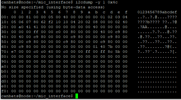
Here is an i2cdump output showing the status of each register after the setup script was run:
Here are my oscilloscope outputs for the SDOUT, FSYNC, and BCLK signals from the PCMD3180 into our RPi.
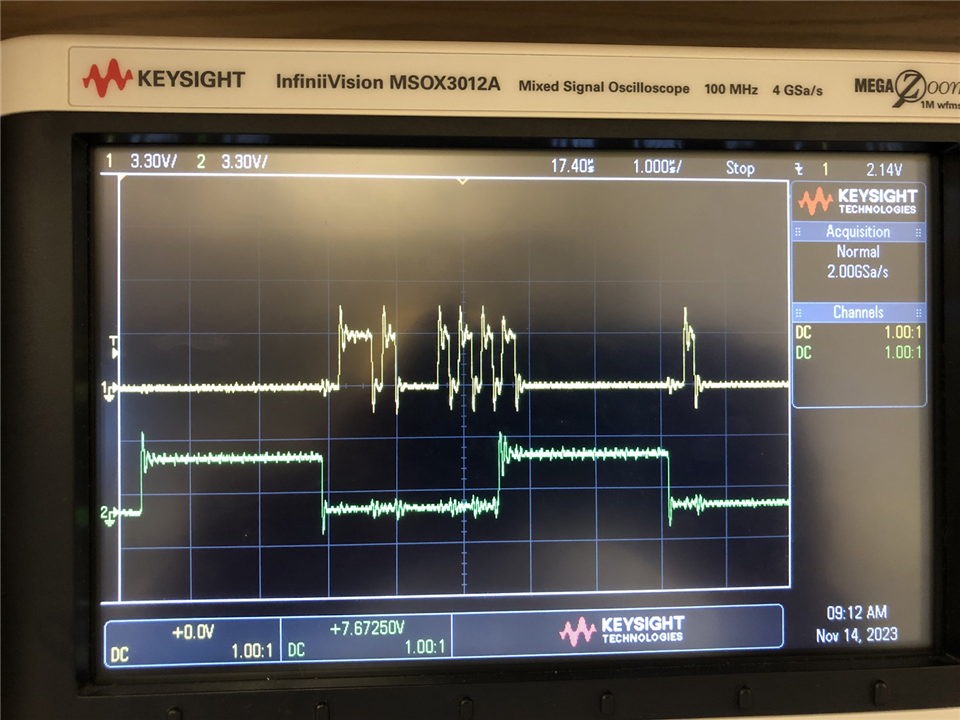
SDOUT on top
FSYNC on bottom: 6.2v peak to peak with noise included. About 5.2us period
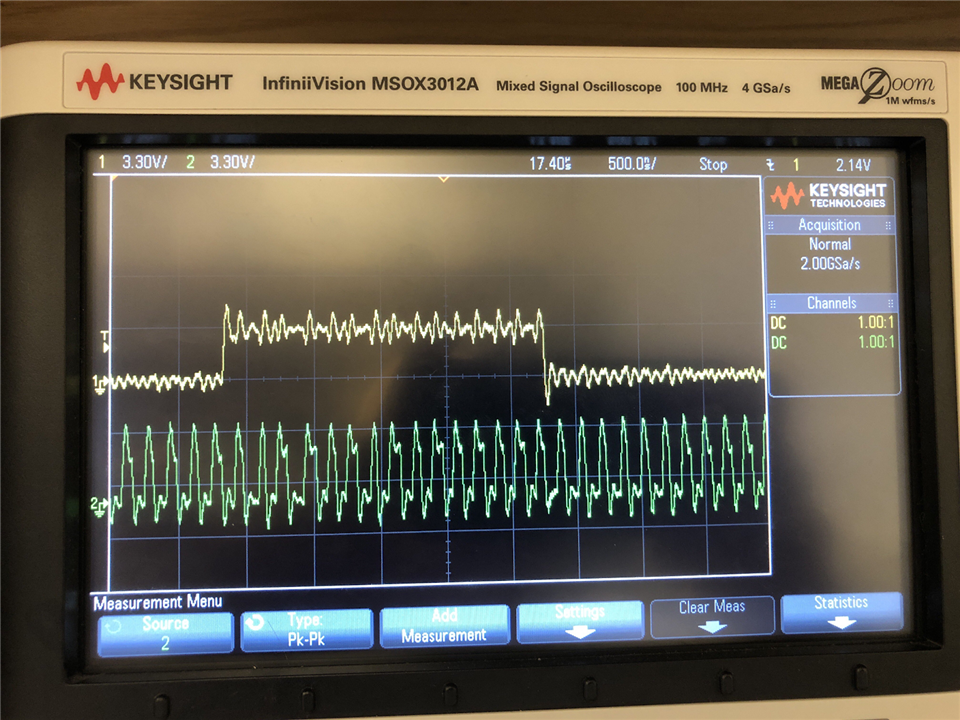
BCLK on bottom - 5.8MHz, 6.2V peak to peak
Aside from that, I am attempting to use the linux arecord command to output the I2S data into a .wav file. At this point I am lost, and am not sure how to proceed to fix this issue. Any help would be appreciated.
