This thread has been locked.

If you have a related question, please click the "Ask a related question" button in the top right corner. The newly created question will be automatically linked to this question.

LM4562: Voltage follower circuit

Part Number: LM4562

I have a question about the gain characteristics and phase characteristics of a voltage follower circuit using LM4562. The simulation results do not match the measurement results. Can you think of any possible reasons for this discrepancy?

the conditions and results below:

■Simulation circuit

I designed the voltage follower circuit to have a gain of approximately 0dB in the frequency range of DC to 20MHz. The load capacitance is assumed to be 1nF, and based on the simulation results, the phase compensation resistor was set to 4.7Ω.

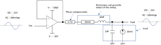
LM4562_voltage follower_231215.TSC
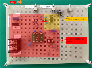
■Board

I created the circuit on a universal PCB. First, I generated a DC voltage  using an LDO and an AC voltage using a function generator. I added these voltages together and applied the resulting voltage to the Vin of the operational amplifier. The V- supply of the OpAmp is powered by a stabilized power supply, generating a DC voltage.Additionally, I have added a 1nF capacitor and a 100kΩ resistor as a load and I am measuring the circuit.(I am creating the PCB to be equivalent to the simulation circuit.)

■Result

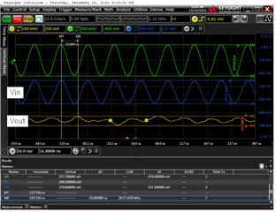
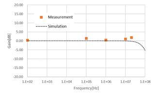
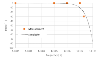
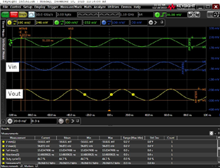
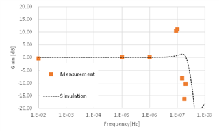
When the frequency of Vin exceeds 1MHz, the gain characteristics and phase characteristics do not match between the measurement results and the simulation results. Additionally, when observing the waveforms of Vin and Vout at 18MHz, Vout was found to be oscillating. What could be the possible factors contributing to the discrepancy between the measurement results and the simulation results in the high-frequency range (above 1MHz)

Gain characteristics

Phase characteristics

Waveform of Vin and Vout at 18MHz

  • Hi Hayashi,

    Thank you for the detailed breakdown of the issue. I do have a few debugging steps we can take to see the potential source of the issue. Seeing the peaking in your measurements it is pointing to instability. It is interesting at these lower frequencies we are seeing these results. I was curious if you completely removed the capacitor at the load what will the behavior be. Is it possible to test this configuration?

    Best Regards,

    Ignacio

  • Hi Ignacio,

    Thank you for your confirmation. We measured the gain and phase characteristics when the load capacitance was set to 0F. As the frequency exceeds 1MHz, the measured values no longer match the simulation values. However, we obtained a 100mVpp sine wave with a frequency of 20MHz, so we believe the results are fine. Can you understand the reason why the measured values and simulation results do not match based on these results?

    The results below:

    Gain characteristics

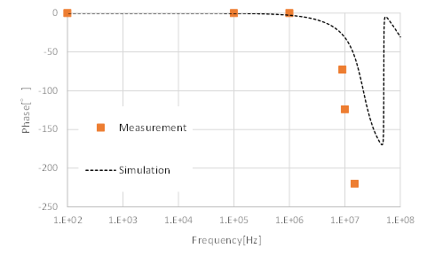
    ・Phase characteristics

    ・Waveform of Vin and Vout at 20MHz

    Best Regards,

    Hayashi

  • Hi Hayashi,

    It seems like there is a chance the amplifier is running into output current limits and causing distortion as it can't output such a high amount of current. However, the peaking is still indicating a potential stability problem. Could you capture the waveforms when there is significant peaking like you captured with 10dB of peaking? As for the differences between results in the model and measurements, models do not do a great job at modeling device behavior across more complex configurations such as those with capacitive loads. Configurations that would also cause distortion in a real life would not be captured all that well as the models do not model distortion. Another consideration is that models do not capture any real-world parasitics that come from boards and other components.

    Best Regards,

    Ignacio   

  • Hi Ignacio,

    Thank you for your confirmation. I apologize for not being able to continue waveform acquisition due to time constraints. As you advised, we will proceed with reselecting the OpAmp and changing the board to a printed circuit board for reevaluation.

    Best Regards,

    Hayashi