This thread has been locked.

If you have a related question, please click the "Ask a related question" button in the top right corner. The newly created question will be automatically linked to this question.

DIT4096: Schematic Check PLZ

Part Number: DIT4096

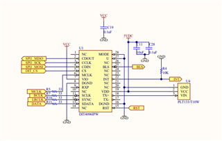
  • Hello Bradly, here are few recommendation/corrections:

    Reset pin is  Active LOW , I suggest to use a pull up resistor to supply

    Use decoupling caps for all supplies ( similar to what yo did for VCC) close to the pins

    INT pin is an Open Drain and thus requires a 10k pull up to VIO

    Regards,

    Arash

  • Hi Arash thanks the micro we use has pull ups built in so I should have shared that info we are having an issue with compatibility with newer consumer audio equipment and we don;'t know why.  Our device plays sometimes and other times when starting the audio stream the equipment does not play the audio stream.  Can you supply reference code for the software bit setup for software mode for this device.  We use an STM micro but any reference code would be appreciated.  Thanks.

  • Bradley,

    Unfortunately we don't have any script for this old device . I have couple of  scripts for similar devices that I can share  with you.

    3652.DIX4192_script.txt
    # set interface mode to i2c fast
    i i2cfast
    # set register page to 0
    w e0 7f 00
    # set gpo 1 thru 4 to logic 1
    w e0 1b 01
    w e0 1c 01
    w e0 1d 01
    w e0 1e 01
    # dir setup
    w e0 0d 00
    w e0 0e 09
    w e0 0f 22
    w e0 10 00
    w e0 11 00
    # dit setup
    w e0 07 f4
    w e0 08 00
    w e0 09 06
    # power up
    w e0 01 26
    
           
    3652.PCM9211_Init.txt
    #**************************************
    #this script is for SPDIF-->RXIN0-->DIR-->MainOutput, Record sound from SPDIF to PC through TAS1020
    
    #So
    #1, Chose RXIN0 to DIR
    #2, Active DIR
    #3, chose DIR output as Mainoutput's source.
    
    #Also HW modification
    #1, Flying to High Level(3.3V) to make sure U7's output is Hi-Z
    #or 2, TAS1020 output logic high on P1.2 I2S enable signal. 
    #**************************************
    
    
    #System RST Control
    #w 80 40 00
    w 80 40 33
    w 80 40 C0
    
    #XTI Source, Clock (SCK/BCK/LRCK) Frequency Setting
    # XTI CLK source 12.288 and BCK 3.072, LRCK 48k = XTI/512
    w 80 31 1A
    w 80 33 22
    w 80 20 00
    w 80 24 00
    #ADC clock source is chosen by REG42
    w 80 26 81
    
    #XTI Source, Secondary Bit/LR Clock (SBCK/SLRCK) Frequency Setting
    w 80 33 22
    
    
    #*********************************************************
    #-------------------------------Start DIR settings---------------------------------------
    #REG. 21h, DIR Receivable Incoming Biphase's Sampling Frequency Range Setting
    w 80 21 00
    
    #REG. 22h, DIR CLKSTP and VOUT delay
    w 80 22 01
    
    #REG. 23h, DIR OCS start up wait time and Process for Parity Error Detection and ERROR Release Wait Time Setting
    w 80 23 04
    
    # REG 27h DIR Acceptable fs Range Setting & Mask
    w 80 27 00
    
    # REG 2Fh, DIR Output Data Format, 24bit I2S mode
    w 80 2F 04
    
    # REG. 30h, DIR Recovered System Clock (SCK) Ratio Setting
    w 80 30 02
    
    #REG. 32h, DIR Source, Secondary Bit/LR Clock (SBCK/SLRCK) Frequency Setting
    w 80 32 22
    
    #REG 34h DIR Input Biphase Signal Source Select and RXIN01 Coaxial Amplifier
    #--PWR down amplifier, Select RXIN2
    #w 80 34 C2
    #--PWR up amplifier, select RXIN0
    w 80 34 00
    #--PWR up amplifier, select RXIN1
    #w 80 34 01
    
    #REG. 37h, Port Sampling Frequency Calculator Measurement Target Setting, Cal and DIR Fs
    w 80 37 00
    #REG 38h rd DIR Fs
    r 80 38 01
    #***********************************************************
    #------------------------------------ End DIR settings------------------------------------------
    
    
    #***********************************************************
    #---------------------------------Start  MainOutput Settings--------------------------------------
    #MainOutput
    #REG. 6Ah, Main Output & AUXOUT Port Control
    w 80 6A 00
    
    #REG. 6Bh, Main Output Port (SCKO/BCK/LRCK/DOUT) Source Setting
    w 80 6B 11
    
    #REG. 6Dh, MPIO_B & Main Output Port Hi-Z Control
    w 80 6D 00
    #***********************************************************
    #------------------------------------ End MainOutput settings------------------------------------------
    
    # read back all registers to ensure GUI integrity
    r 80 20 5E

    The compatibility might be a windows or OS issue and I am not the right person to comment on possible causes. 

     For software questions may be you should open a new post;  but make sure the title is descriptive so it goes to the software team who might be able to give you some suggestions.

     Regards,

    Arash