


Dear TI Teams,
We have some question about the PA use of TPA2016D2. We have noticed that there some relevant descriptions in the datesheet, but the explanations are seems not very specific. Can you help to check the following questions?
1) We would like to focus on the understanding the issue of PA's gain and mode selection for registers (Figure 2 and Figure 3 are different modes in my understanding, if not accurately understood, please point them out). Which of Figure 1 are related to these two and how should they be configured?
2) Does Figure 2 and Figure 3 refer to different modes of PA, and how are they matched specifically?
3) Figure 4 and Figure 5 are the configurations of our project. Could you help to check if there are any issues?
4) What would be the impact of reducing the gain of the front-end chip and increasing the gain on the PA side?
Figure 1:
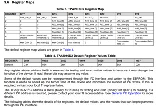
Figure 2:
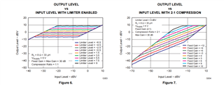
Figure 3:
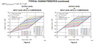
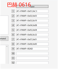
Figure 4:
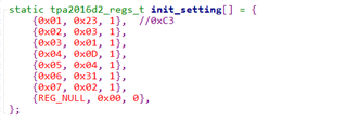
Figure 5:
Thanks,
Kind Regards
