This thread has been locked.
If you have a related question, please click the "Ask a related question" button in the top right corner. The newly created question will be automatically linked to this question.
Hi,
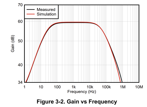
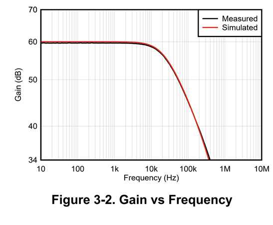
I want to know the proper configuration to connect a low-frequency antenna (L = 12mH @ Rdc = 7.5Ω @ Cp = ~ 60pF) to an opa1656 amplifier with a required gain of around 200~300 and a bandwidth of approximately 3kHz - 300kHz, while minimizing noise, is needed to add entry level such us JFET JFE2140?
Best Regards.
Hey Itmar,
I wrote an application note (link below) on using the JFE2140 in a composite configuration for ultra low noise. Within the app note I demonstrate how to set the gain. The high input impedance of the JFET certainly helps with high inductive sensors such as the antenna.
Best Regards,
Chris Featherstone
Hi, Chris.
Which low noise amplifier should I use? Is the OPA1656 a suitable option?
Should I opt for a single-ended or differential configuration?
Can you provide guidance on the best direction to pursue?
All the best,
Itamar Shamay
Hardware Engineer
Exodigo.
Hi Itmar,
Was the differential configuration in the link below not suitable for your application? If not you may consider using the single ended configuration from my app note. Is your sensor a single ended sensor or differential? This will determine if you need a single ended or differential input.
The main reason to choose the JFET input is to have a high input impedance with low current noise. If you decide that a single ended input is right for your application I would recommend a bipolar amplifier such as the OPA202 after the discrete JFET. Bipolar amplifiers tend to have higher current noise and low voltage noise. The current noise is what we are trying to avoid interacting with a high impedance sensor. High current noise interacting with high source impedance translates to additional voltage noise. You can replace the front end of a bipolar amp with a discrete JFET and benefit by the low current noise from the JFET followed by a bipolar amp. The bipolar amp would now not be interacting with the sensor.
Best Regards,
Chris Featherstone
Thank you for the answer.
My sensor is a low-frequency antenna, and I have the option to use either a differential or single-ended configuration.
Regarding the INA849 design that you recommended, I conducted tests and found that it did not yield the best SNR configuration. The test involved using two 9V batteries enclosed in metal shielding, and I transmitted frequencies ranging from 1KHz to 250KHz. The simulation results did not align with the outcomes observed during the actual test.
Could it be that the SPICE model of my antenna is not accurate?
Hey Itmar,
It is hard to say why they would not have aligned however that is surprising. It is possible the antenna model is not accurate. My other suspicions would be the biasing of the JFETs, common mode input voltage was exceeded or output signal was exceeded.
Differential signaling benefits from common mode rejection when the input components are balanced and matched. It is possible the biasing of the JFETs was different due to component tolerance in which case the CMRR could be compromised depending on how far off they may have been.
My JFE150EVM and JFE2140EVM were both measured. They are single ended in and ultra low noise. The corresponding app notes go along with the EVM for a description on the theory.
JFE150:
App Note:
EVM
https://www.ti.com/tool/JFE150EVM
JFE2140
App Note
https://www.ti.com/lit/an/sboa563/sboa563.pdf?ts=1715330609473
EVM
https://www.ti.com/tool/JFE2140EVM#tech-docs
Alternatively you may use a single JFET op amp such as the OPA145 in a regular op amp gain configuration with a single ended input.
https://www.ti.com/lit/ds/symlink/opa145.pdf
Best Regards,
Chris Featherstone
Hey Itmar,
To follow up on my last response. When you tested out the INA design from the previous INA849 post, did you layout a PCB to test?
Best Regards,
Chris Featherstone