This thread has been locked.

If you have a related question, please click the "Ask a related question" button in the top right corner. The newly created question will be automatically linked to this question.

TLV320AIC3254-Q1: TLV320AIC3254-Q1: There is no DOUT/MFP2 output

Part Number: TLV320AIC3254-Q1
Other Parts Discussed in Thread: TLV320AIC3254

Tool/software:

Dear TI, 

Please reference https://e2e.ti.com/support/audio-group/audio/f/audio-forum/1348902/tlv320aic3254-q1-tlv320aic3254-q1-bringup-issue/5195835#5195835

We are bringup TLV320AIC3254 at QCOM platform.

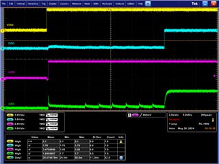
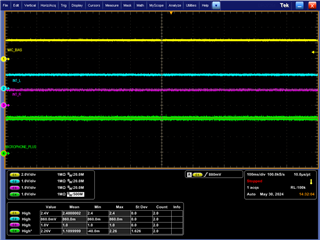
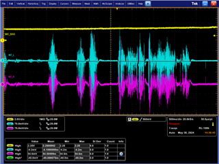
However, we can not detection the DOUT/MFP2  output  from IC

PLease check the following information about ICreg dump page0/1

/ # i2cset -fy 2 0x18 0x00 0x00 b
WARNING! This program can confuse your I2C bus, cause data loss and worse!
I will write to device file /dev/i2c-2, chip address 0x18, data address
0x00, data 0x00, mode byte.
Continue? [Y/n] y
/ # i2cdump -fy 2 0x18
No size specified (using byte-data access)
WARNING! This program can confuse your I2C bus, cause data loss and worse!
I will probe file /dev/i2c-2, address 0x18, mode byte
Continue? [Y/n] y
     0  1  2  3  4  5  6  7  8  9  a  b  c  d  e  f    0123456789abcdef
00: 00 00 60 00 07 92 20 00 00 00 00 88 82 00 80 02    ..`.?? ....??.??
10: 00 08 88 82 80 01 00 04 00 00 01 00 00 01 84 00    .?????.?..?..??.
20: 00 00 00 00 cc 00 00 00 00 00 00 00 00 00 00 00    ....?...........
30: 00 00 00 00 08 12 03 02 04 00 00 00 01 01 00 14    ....?????...??.?
40: 0c d8 d8 00 6f 38 00 00 00 00 00 ee 10 d8 7e e3    ???.o8.....???~?
50: 00 c0 88 00 00 00 00 00 7f 00 00 00 00 00 00 00    .??.....?.......
60: 7f 00 00 00 00 00 00 00 00 00 00 00 00 00 00 00    ?...............
70: 00 00 00 00 00 00 00 00 00 00 00 00 00 00 00 00    ................
80: 00 00 00 00 00 00 00 00 00 00 00 00 00 00 00 00    ................
90: 00 00 00 00 00 00 00 00 00 00 00 00 00 00 00 00    ................
a0: 00 00 00 00 00 00 00 00 00 00 00 00 00 00 00 00    ................
b0: 00 00 00 00 00 00 00 00 00 00 00 00 00 00 00 00    ................
c0: 00 00 00 00 00 00 00 00 00 00 00 00 00 00 00 00    ................
d0: 00 00 00 00 00 00 00 00 00 00 00 00 00 00 00 00    ................
e0: 00 00 00 00 00 00 00 00 00 00 00 00 00 00 00 00    ................
f0: 00 00 00 00 00 00 00 00 00 00 00 00 00 00 00 00    ................
/ #
/ # i2cset -fy 2 0x18 0x00 0x01 b
WARNING! This program can confuse your I2C bus, cause data loss and worse!
I will write to device file /dev/i2c-2, chip address 0x18, data address
0x00, data 0x01, mode byte.
Continue? [Y/n] y
/ # i2cdump -fy 2 0x18
No size specified (using byte-data access)
WARNING! This program can confuse your I2C bus, cause data loss and worse!
I will probe file /dev/i2c-2, address 0x18, mode byte
Continue? [Y/n] y
     0  1  2  3  4  5  6  7  8  9  a  b  c  d  e  f    0123456789abcdef
00: 01 00 01 00 00 00 00 00 00 00 00 10 00 00 00 00    ?.?........?....
10: 40 40 40 40 00 00 00 00 00 00 00 00 00 00 00 00    @@@@............
20: 00 00 00 00 00 00 00 00 00 00 00 00 00 00 00 00    ................
30: 00 00 00 68 40 00 40 40 00 40 00 00 00 00 03 00    ...h@.@@.@....?.
40: 00 00 00 00 00 00 00 00 00 00 00 00 00 00 00 00    ................
50: 00 00 00 00 00 00 00 00 00 00 00 00 00 00 00 00    ................
60: 00 00 00 00 00 00 00 00 00 00 00 00 00 00 00 00    ................
70: 00 00 00 00 00 00 00 00 00 00 00 05 00 00 00 00    ...........?....
80: 00 00 00 00 00 00 00 00 00 00 00 00 00 00 00 00    ................
90: 00 00 00 00 00 00 00 00 00 00 00 00 00 00 00 00    ................
a0: 00 00 00 00 00 00 00 00 00 00 00 00 00 00 00 00    ................
b0: 00 00 00 00 00 00 00 00 00 00 00 00 00 00 00 00    ................
c0: 00 00 00 00 00 00 00 00 00 00 00 00 00 00 00 00    ................
d0: 00 00 00 00 00 00 00 00 00 00 00 00 00 00 00 00    ................
e0: 00 00 00 00 00 00 00 00 00 00 00 00 00 00 00 00    ................
f0: 00 00 00 00 00 00 00 00 00 00 00 00 00 00 00 00    ................
/ #

  • Dear Ti, 

    Do you have any update?

    Thank you very much

  • Hi Daniel,

    Yesterday was a TI holiday in the United States. Thank you for your patience.

    I see the ADCs are powered on and unmuted in your register map. Are all power supplies/I2S clocks powered up and given to the codec?

    When measuring DOUT, is there any data toggling or is it stuck low?

    Best regards,
    Jeff McPherson

  • Dear Ti, 

    Figure 1 is codec Power on sequece

    Figure 2 is  Microphone related DC voltage

    Figure 3 is  switch the microphone signal measured by the oscilloscope to AC mode

    Figure 4 is Microphone signal VS I2S signal

    When speaking into the microphone, there is no signal change in I2S output !

    Figure 5 is I2S' frequency

    Best regards,
    CH Wen

  • Hi CH Wen,

    Please try the following script below and see if you get any activity from the ADC DOUT. I also noticed you have one of the clocks labelled as SCK. Is that connected to the BCLK pin of the device?

    Assumption AVdd = 1.8V, DVdd = 1.8V MCLK = 12.288MHz Default settings used. PLL Disabled I2S
    Interface with 16bit Word Length. AOSR 128 PRB_R1 PTM_R4
    # Initialize to Page 0
    w 30 00 00
    # S/W Reset to initialize all registers
    w 30 01 01
    # Power up NADC divider with value 1
    w 30 12 81
    # Power up MADC divider with value 2
    w 30 13 82
    # Program OSR for ADC to 128
    w 30 14 80
    # Select ADC PRB_R1
    w 30 3d 01
    # Select Page 1
    w 30 00 01
    # Disable Internal Crude AVdd in presence of external AVdd supply or before
    # powering up internal AVdd LDO
    w 30 01 08
    # Enable Master Analog Power Control
    w 30 02 00
    # Set the input common mode to 0.9V
    w 30 0a 00
    # Select ADC PTM_R4
    w 30 3d 00
    # Set MicPGA startup delay to 3.1ms
    w 30 47 32
    # Set the REF charging time to 40ms
    w 30 7b 01
    # Route IN1L to LEFT_P with 20K input impedance
    w 30 34 80
    # Route Common Mode to LEFT_M with impedance of 20K
    w 30 36 80
    # Route IN1R to RIGHT_P with input impedance of 20K
    w 30 37 80
    # Route Common Mode to RIGHT_M with impedance of 20K
    w 30 39 80
    # Unmute Left MICPGA, Gain selection of 6dB to make channel gain 0dB
    # Register of 6dB with input impedance of 20K => Channel Gain of 0dB
    w 30 3b 0c
    # Unmute Right MICPGA, Gain selection of 6dB to make channel gain 0dB
    # Register of 6dB with input impedance of 20K => Channel Gain of 0dB
    w 30 3c 0c
    # Select Page 0
    w 30 00 00
    # Power up Left and Right ADC Channels
    w 30 51 c0
    # Unmute Left and Right ADC Digital Volume Control.
    w 30 52 00
    

    Best regards,
    Jeff McPherson

  • Dear Jeff

    base on the reg dump, whick one register is difference? 

    Which register was wrong?

    We use linux platform,

    How to modify the driver to config these register?

    or How to config via i2cset tool?

    Thank you very much

  • Dear Ti, 

    It's BCLK.

    Best regards,
    CH Wen

  • Dear Jeff,

    After setting the script, I2S_DOUT has signal output, but the MICBIAS will become 0.02V.

    If we don't used the script, it can be measured to 2.2V.

  • Hi,

    The clock tree is different in the script. It's not a single register issue.

    The script is missing MICBIAS enabled. To enable MICBIAS add this line after line 23: w 30 33 60

    I will move this ticket to our software team to aid you in editing the driver.

    Best regards,
    Jeff McPherson

  • Dear Jeff

    We do following config,

    The bias still not work, do you have any comment?

    Thank you very much

    i2cset -fy 2 0x18 0x00 0x00 b
    i2cset -fy 2 0x18 0x01 0x01 b
    i2cset -fy 2 0x18 0x12 0x81 b
    i2cset -fy 2 0x18 0x13 0x82 b
    i2cset -fy 2 0x18 0x14 0x80 b
    i2cset -fy 2 0x18 0x3d 0x01 b
    i2cset -fy 2 0x18 0x00 0x01 b
    i2cset -fy 2 0x18 0x01 0x08 b
    i2cset -fy 2 0x18 0x02 0x00 b
    i2cset -fy 2 0x18 0x0a 0x00 b
    i2cset -fy 2 0x18 0x33  0x60 b
    i2cset -fy 2 0x18 0x3d 0x00 b
    i2cset -fy 2 0x18 0x47 0x32 b
    i2cset -fy 2 0x18 0x7b 0x01 b
    i2cset -fy 2 0x18 0x34 0x80 b
    i2cset -fy 2 0x18 0x36 0x80 b
    i2cset -fy 2 0x18 0x37 0x80 b
    i2cset -fy 2 0x18 0x39 0x80 b
    i2cset -fy 2 0x18 0x3b 0x0c b
    i2cset -fy 2 0x18 0x3c 0x0c b
    i2cset -fy 2 0x18 0x00 0x00 b
    i2cset -fy 2 0x18 0x51 0xc0 b
    i2cset -fy 2 0x18 0x52 0x00 b
    

  • Dear Jeff

    Do you or your software team have any update?

    Thank you very much

  • Can you tell me which code you used?

  • Dear Ding

    You can get the code from following link
    https://drive.google.com/file/d/1oKfScjjOfpO01DXnulHqVuiv7o8t-tIs/view?usp=sharing

     There are some modification form your member Lu, Kevin.

  • So the register setting Jeff offered can't work, right? 

  • Dear Ding

    The Jeff can make the I2S Tx have signal, but the bias will be close
    We can not reopen the bias again

  • Tell me which register has make the I2S Tx have signal, I can check how to add the kcontrol in the code.

    When recording, what amixer commands do you used? And do you set the aic3254 as master or slave?

  • The register is taht Jeff provide.

    The aic3254 is the save mode

  • Dear Ding

    Dp you have any update?

  • Hi Daniel,

    Pls provide your registers dump after recording.

  • / # i2cdump -fy 2 0x18
    No size specified (using byte-data access)
    WARNING! This program can confuse your I2C bus, cause data loss and worse!
    I will probe file /dev/i2c-2, address 0x18, mode byte
    Continue? [Y/n] y
         0  1  2  3  4  5  6  7  8  9  a  b  c  d  e  f    0123456789abcdef
    00: 00 00 60 00 07 92 20 00 00 00 00 88 82 00 80 02    ..`.?? ....??.??
    10: 00 08 88 82 80 01 00 04 00 00 01 00 00 01 84 00    .?????.?..?..??.
    20: 00 00 00 00 cc 00 00 00 00 00 00 00 00 00 00 00    ....?...........
    30: 00 00 00 00 08 12 03 02 04 00 00 00 01 01 00 14    ....?????...??.?
    40: 0c d8 d8 00 6f 38 00 00 00 00 00 ee 10 d8 7e e3    ???.o8.....???~?
    50: 00 c0 88 00 00 00 00 00 7f 00 00 00 00 00 00 00    .??.....?.......
    60: 7f 00 00 00 00 00 00 00 00 00 00 00 00 00 00 00    ?...............
    70: 00 00 00 00 00 00 00 00 00 00 00 00 00 00 00 00    ................
    80: 00 00 00 00 00 00 00 00 00 00 00 00 00 00 00 00    ................
    90: 00 00 00 00 00 00 00 00 00 00 00 00 00 00 00 00    ................
    a0: 00 00 00 00 00 00 00 00 00 00 00 00 00 00 00 00    ................
    b0: 00 00 00 00 00 00 00 00 00 00 00 00 00 00 00 00    ................
    c0: 00 00 00 00 00 00 00 00 00 00 00 00 00 00 00 00    ................
    d0: 00 00 00 00 00 00 00 00 00 00 00 00 00 00 00 00    ................
    e0: 00 00 00 00 00 00 00 00 00 00 00 00 00 00 00 00    ................
    f0: 00 00 00 00 00 00 00 00 00 00 00 00 00 00 00 00    ................

    Based on the page0, the reg 0x52 should be 0x00, 0x88 means ADC muted, you can enter below commands after recording with the previous amixer setting.

    #i2cset -fy 0 0x18 0x52 0x00 b #unmute ADC channels

    #i2cset -fy 0 0x18 0x53 0x28 b #20db volume gain

    #i2cset -fy 0 0x18 0x00 0x01 b

    #i2cset -fy 0 0x18 0x3b 0x10 b

    #i2cset -fy 0 0x18 0x00 0x00 b 

    Kindly share the registers dump if it doesn't work

    Thanks

  • Dear Kevin, Ding,

    Please check the register dump after Ding's register script

    Thank you very much

    / # i2cset -fy 2 0x18 0x00 0x00 b
    WARNING! This program can confuse your I2C bus, cause data loss and worse!
    I will write to device file /dev/i2c-2, chip address 0x18, data address
    0x00, data 0x00, mode byte.
    Continue? [Y/n] Y
    / # i2cdump -fy 2 0x18
    No size specified (using byte-data access)
    WARNING! This program can confuse your I2C bus, cause data loss and worse!
    I will probe file /dev/i2c-2, address 0x18, mode byte
    Continue? [Y/n] Y
         0  1  2  3  4  5  6  7  8  9  a  b  c  d  e  f    0123456789abcdef
    00: 00 00 60 00 00 11 04 00 00 00 00 01 01 00 80 02    ..`..??....??.??
    10: 00 08 81 82 80 01 00 04 00 00 01 00 00 00 01 00    .?????.?..?...?.
    20: 00 00 00 00 cc 00 00 00 00 00 00 00 c0 00 80 00    ....?.......?.?.
    30: 00 00 00 00 00 12 03 02 02 00 00 00 01 01 00 14    .....????...??.?
    40: 0c 00 00 00 6f 38 00 00 00 00 00 ee 10 d8 7e e3    ?...o8.....???~?
    50: 00 c0 00 00 00 00 00 00 7f 00 00 00 00 00 00 00    .?......?.......
    60: 7f 00 00 00 00 00 00 00 00 00 00 00 00 00 00 00    ?...............
    70: 00 00 00 00 00 00 00 00 00 00 00 00 00 00 00 00    ................
    80: 00 00 00 00 00 00 00 00 00 00 00 00 00 00 00 00    ................
    90: 00 00 00 00 00 00 00 00 00 00 00 00 00 00 00 00    ................
    a0: 00 00 00 00 00 00 00 00 00 00 00 00 00 00 00 00    ................
    b0: 00 00 00 00 00 00 00 00 00 00 00 00 00 00 00 00    ................
    c0: 00 00 00 00 00 00 00 00 00 00 00 00 00 00 00 00    ................
    d0: 00 00 00 00 00 00 00 00 00 00 00 00 00 00 00 00    ................
    e0: 00 00 00 00 00 00 00 00 00 00 00 00 00 00 00 00    ................
    f0: 00 00 00 00 00 00 00 00 00 00 00 00 00 00 00 00    ................
    / # i2cset -fy 2 0x18 0x00 0x01 b
    WARNING! This program can confuse your I2C bus, cause data loss and worse!
    I will write to device file /dev/i2c-2, chip address 0x18, data address
    0x00, data 0x01, mode byte.
    Continue? [Y/n] Y
    / # i2cdump -fy 2 0x18
    No size specified (using byte-data access)
    WARNING! This program can confuse your I2C bus, cause data loss and worse!
    I will probe file /dev/i2c-2, address 0x18, mode byte
    Continue? [Y/n] Y
         0  1  2  3  4  5  6  7  8  9  a  b  c  d  e  f    0123456789abcdef
    00: 01 08 00 00 00 00 00 00 00 00 00 10 00 00 00 00    ??.........?....
    10: 40 40 40 40 00 00 00 00 00 00 00 00 00 00 00 00    @@@@............
    20: 00 00 00 00 00 00 00 00 00 00 00 00 00 00 00 00    ................
    30: 00 00 00 60 80 00 80 80 00 80 00 0c 0c 00 03 00    ...`?.??.?.??.?.
    40: 00 00 00 00 00 00 00 32 00 00 00 00 00 00 00 00    .......2........
    50: 00 00 00 00 00 00 00 00 00 00 00 00 00 00 00 00    ................
    60: 00 00 00 00 00 00 00 00 00 00 00 00 00 00 00 00    ................
    70: 00 00 00 00 00 00 00 00 00 00 00 01 00 00 00 00    ...........?....
    80: 00 00 00 00 00 00 00 00 00 00 00 00 00 00 00 00    ................
    90: 00 00 00 00 00 00 00 00 00 00 00 00 00 00 00 00    ................
    a0: 00 00 00 00 00 00 00 00 00 00 00 00 00 00 00 00    ................
    b0: 00 00 00 00 00 00 00 00 00 00 00 00 00 00 00 00    ................
    c0: 00 00 00 00 00 00 00 00 00 00 00 00 00 00 00 00    ................
    d0: 00 00 00 00 00 00 00 00 00 00 00 00 00 00 00 00    ................
    e0: 00 00 00 00 00 00 00 00 00 00 00 00 00 00 00 00    ................
    f0: 00 00 00 00 00 00 00 00 00 00 00 00 00 00 00 00    ................

  • Dear Kevin

    The following dump is after your register write

    / # i2cset -fy 2 0x18 0x00 0x00 b
    / # i2cdump -fy 2 0x18
         0  1  2  3  4  5  6  7  8  9  a  b  c  d  e  f    0123456789abcdef
    00: 00 00 60 00 07 12 20 00 00 00 00 08 02 00 80 02    ..`.?? ....??.??
    10: 00 08 08 02 80 01 00 04 00 00 01 00 00 01 04 00    .?????.?..?..??.
    20: 00 00 00 00 cc 00 00 00 00 00 00 00 00 00 00 00    ....?...........
    30: 00 00 00 00 08 12 03 02 04 00 00 00 01 01 00 14    ....?????...??.?
    40: 0c d8 d8 00 6f 38 00 00 00 00 00 ee 10 d8 7e e3    ???.o8.....???~?
    50: 00 00 88 28 00 00 00 00 7f 00 00 00 00 00 00 00    ..?(....?.......
    60: 7f 00 00 00 00 00 00 00 00 00 00 00 00 00 00 00    ?...............
    70: 00 00 00 00 00 00 00 00 00 00 00 00 00 00 00 00    ................
    80: 00 00 00 00 00 00 00 00 00 00 00 00 00 00 00 00    ................
    90: 00 00 00 00 00 00 00 00 00 00 00 00 00 00 00 00    ................
    a0: 00 00 00 00 00 00 00 00 00 00 00 00 00 00 00 00    ................
    b0: 00 00 00 00 00 00 00 00 00 00 00 00 00 00 00 00    ................
    c0: 00 00 00 00 00 00 00 00 00 00 00 00 00 00 00 00    ................
    d0: 00 00 00 00 00 00 00 00 00 00 00 00 00 00 00 00    ................
    e0: 00 00 00 00 00 00 00 00 00 00 00 00 00 00 00 00    ................
    f0: 00 00 00 00 00 00 00 00 00 00 00 00 00 00 00 00    ................
    / # i2cset -fy 2 0x18 0x00 0x01 b
    / # i2cdump -fy 2 0x18
         0  1  2  3  4  5  6  7  8  9  a  b  c  d  e  f    0123456789abcdef
    00: 01 00 01 00 00 00 00 00 00 00 00 10 00 00 00 00    ?.?........?....
    10: 40 40 40 40 00 00 00 00 00 00 00 00 00 00 00 00    @@@@............
    20: 00 00 00 00 00 00 00 00 00 00 00 00 00 00 00 00    ................
    30: 00 00 00 00 40 00 40 40 00 40 00 10 00 00 00 00    ....@.@@.@.?....
    40: 00 00 00 00 00 00 00 00 00 00 00 00 00 00 00 00    ................
    50: 00 00 00 00 00 00 00 00 00 00 00 00 00 00 00 00    ................
    60: 00 00 00 00 00 00 00 00 00 00 00 00 00 00 00 00    ................
    70: 00 00 00 00 00 00 00 00 00 00 00 05 00 00 00 00    ...........?....
    80: 00 00 00 00 00 00 00 00 00 00 00 00 00 00 00 00    ................
    90: 00 00 00 00 00 00 00 00 00 00 00 00 00 00 00 00    ................
    a0: 00 00 00 00 00 00 00 00 00 00 00 00 00 00 00 00    ................
    b0: 00 00 00 00 00 00 00 00 00 00 00 00 00 00 00 00    ................
    c0: 00 00 00 00 00 00 00 00 00 00 00 00 00 00 00 00    ................
    d0: 00 00 00 00 00 00 00 00 00 00 00 00 00 00 00 00    ................
    e0: 00 00 00 00 00 00 00 00 00 00 00 00 00 00 00 00    ................
    f0: 00 00 00 00 00 00 00 00 00 00 00 00 00 00 00 00    ................

  • Hi Daniel,

    I recommended you to set reg0x52 to be 0x00, and don't change reg 0x51 to be 0x00, why's still incorrect?

    Kevin

  • Dear Kevin, 

    It possible i did not change to page 0
    Should  i use Jeff's script first?

    Thank you very much

  • No need, you can try my recommendation first

  • Dear Kevin, 
    please check the following register dump
    However, the bias become 0 after i start capture data

    / # i2cset -fy 2 0x18 0x00 0x00 b
    / # i2cset -fy 2 0x18 0x52 0x00 b
    / # i2cset -fy 2 0x18 0x53 0x28 b
    / # i2cset -fy 2 0x18 0x00 0x01 b
    / # i2cset -fy 2 0x18 0x3b 0x10 b
    / # i2cset -fy 2 0x18 0x00 0x00 b
    / #
    / #
    / #
    / # i2cdump -fy 2 0x18
         0  1  2  3  4  5  6  7  8  9  a  b  c  d  e  f    0123456789abcdef
    00: 00 00 60 00 07 92 20 00 00 00 00 88 82 00 80 02    ..`.?? ....??.??
    10: 00 08 88 82 80 01 00 04 00 00 01 00 00 01 84 00    .?????.?..?..??.
    20: 00 00 00 00 44 00 00 00 00 00 00 00 00 00 00 00    ....D...........
    30: 00 00 00 00 08 12 03 02 04 00 00 00 01 01 00 14    ....?????...??.?
    40: 0c d8 d8 00 6f 38 00 00 00 00 00 ee 10 d8 7e e3    ???.o8.....???~?
    50: 00 c0 00 28 00 00 00 00 7f 00 00 00 00 00 00 00    .?.(....?.......
    60: 7f 00 00 00 00 00 00 00 00 00 00 00 00 00 00 00    ?...............
    70: 00 00 00 00 00 00 00 00 00 00 00 00 00 00 00 00    ................
    80: 00 00 00 00 00 00 00 00 00 00 00 00 00 00 00 00    ................
    90: 00 00 00 00 00 00 00 00 00 00 00 00 00 00 00 00    ................
    a0: 00 00 00 00 00 00 00 00 00 00 00 00 00 00 00 00    ................
    b0: 00 00 00 00 00 00 00 00 00 00 00 00 00 00 00 00    ................
    c0: 00 00 00 00 00 00 00 00 00 00 00 00 00 00 00 00    ................
    d0: 00 00 00 00 00 00 00 00 00 00 00 00 00 00 00 00    ................
    e0: 00 00 00 00 00 00 00 00 00 00 00 00 00 00 00 00    ................
    f0: 00 00 00 00 00 00 00 00 00 00 00 00 00 00 00 00    ................

  • First of all, you should start capture data, then execute these commands, because the manually setting will change the driver process.

  • Dear Kevin

    Sofar, the sound can be recording.

    After i start capture, i need to type the amixer command again.

    and type this two commands

    i2cset -fy 2 0x18 0x00 0x00 b

    i2cset -fy 2 0x18 0x52 0x00 b

    after this action, the I2S Tx can outout the data,

    Thank you very much fot great help

    Now, How i integrate the "i2cset -fy 2 0x18 0x52 0x00 b" to driver?

    Thank you 

  • tlv320aic3x-linux-audio-routing-path-setting.pdf

    Hi Daniel,

    Actually, I did tell you the correct amixer setting as attachment, could you confirm it in your side? just as below:

    • 'ADCFGA Left Mute Switch’ => on
    • 'ADCFGA Right Mute Switch’ => on (if needed)
    • 'Mic PGA Switch’ => on,on
    • "ADC Level Volume“ => value
    • "PGA Level Volume“ => value
    • "IN1_R to Left Mixer Positive Resistor“ => "10 kOhm"
    • "IN1_R to Right Mixer Positive Resistor“ => "10 kOhm"
  • Following is the miser i use

    amixer -c0 cset name='ADCFGA Left Mute Switch' on
    amixer -c0 cset name='ADCFGA Right Mute Switch' on
    amixer -c0 cset name='Mic PGA Switch' on,on

    amixer -c0 cset name='IN1_L to Left Mixer Positive Resistor' 1
    amixer -c0 cset name='IN1_R to Right Mixer Positive Resistor' 1

    amixer -c0 cset name='CM_L to Left Mixer Negative Resistor' 1
    amixer -c0 cset name='CM_R to Right Mixer Negative Resistor' 1

    Did i miss this two?

    • "ADC Level Volume“ => value
    • "PGA Level Volume“ => value

    Even i change this two, the 0x52 will not be change

    Thank you

  • You need to choose resistor also:

    • "IN1_R to Left Mixer Positive Resistor“ => "10 kOhm"
    • "IN1_R to Right Mixer Positive Resistor“ => "10 kOhm"

    Volume controls are optional unless you want bigger recording data.