TAS6584-Q1: Audio Waveform Inquiry

Part Number: TAS6584-Q1
Other Parts Discussed in Thread: LM5123-Q1

Tool/software:

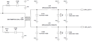
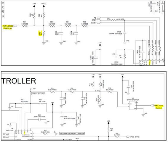
I am testing using TAS6584-Q1 2ea and LM5123-Q1.

Audio input uses TDM and output channels use 4 channels each, for a total of 8Ch.

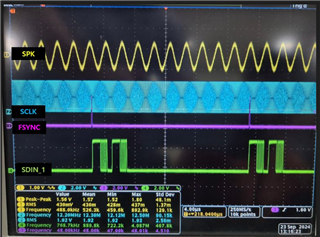
Even if no signal is input to Audio Input, the following waveform is generated in SPK(OUT1).

If a sound source signal is input to Audio Input, a sound with noise is played.

The register settings are as follows.

Address 0x21, Data 0x14 / TDM Mode
Address 0x23, Data 0x0F / 32bit
Address 0x03, Data 0x44 / CH1, CH2 Play

I would like to ask for help on why a strange waveform is generated on the speaker side.

And additionally, please check if the register settings are correct.

  • Hello,

    The signal in your screenshot of your oscilloscope shows data present on Channels 1 and 2.  I would expect to see signal out on these two channels.  

    The Yellow trace is the filtered PWM signal.  This is 480kHz and is normal to see on the oscilloscope, but the speakers will not see it.  430mVrms is large, what are the values of your LC filter.

    Your three settings are correct

    Regards,
    Gregg Scott

  • Hello. Gregg Scott

    The values ​​for the LC Filter are:
    10uH + 1uF + 1uH + 10nF

  • Hello. Gregg Scott

    I have one more question.

    When noise is introduced to the AMP1_GPIO3 line (Class H Line), the SW side FET of the Boost IC is damaged due to overcurrent.

    For example, when the AMP1_GPIO3 line is touched by hand.

    If a pull-down resistor (R72) is added to the AMP1_GPIO3 line, it will not be damaged.

    Will Class H work even if a pull-down resistor is added?

    Or do I need to add something?

    The above problem was tested when the AMP's register settings were not performed.

  • Hi

    The above problem was tested when the AMP's register settings were not performed.

    If you don't give the correct register settings, the classH function is not enabled. GPIO would be Hi-Z state.

    When noise is introduced to the AMP1_GPIO3 line (Class H Line), the SW side FET of the Boost IC is damaged due to overcurrent.

    For example, when the AMP1_GPIO3 line is touched by hand.

    If a pull-down resistor (R72) is added to the AMP1_GPIO3 line, it will not be damaged.

    Then from your schematic, the TRK of LM5123 is totally open circuit, will be very sensitive to the noise. Give it a pull low, or pull up all should work.

    Will Class H work even if a pull-down resistor is added?

    Usually we recommend the RC network as below, have pull up would be fine.