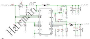
Other Parts Discussed in Thread: TLV320ADC5140, TPS65131, TPS62933
Tool/software:
Hi team,
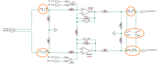
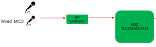
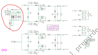
My customer use OPA1678 to get single end to difference circuit, input is wired microphone audio, and output audio data is changed to difference which will be sent to ADC5140,
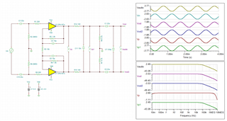
When I input 2Vrms sine waveform, output waveform will be distortion (THD is about 1.6%), if I reduce input to 1.6Vrms, distortion will disappear, can you help check if there is something wrong with OPA1678 circuit?
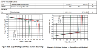
Is that because of carrying load capacity?
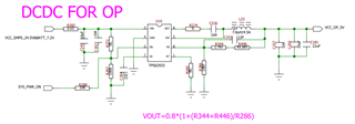
Below is OPA1678 circuit, pls see U24 device at page2
Partyband M_EV1(ADC5140) SCH.pdf
BR
Amber