Tool/software:
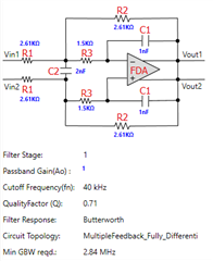
Hello, In an amplification circuit using an op amp, the value of the feedback resistance between the (-) input and output terminals will be different for each amplification circuit. In an amplification circuit using an op amp, the value of the feedback resistance between the (-) input and output terminals will be different for each amplification circuit. If this feedback resistor value is low, the current flowing through the feedback resistor at the output of the op amp will be high, so the op amp's output 2 / 5 impedance must be designed to be low. In other words, the op amp's output drive capability must be good enough to drive the feedback resistor. More precisely, it is more accurate to calculate that the feedback resistor value and the resistance value of the next load impedance of the op amp are in parallel. An op amp designed with a low output impedance is called a low impedance op amp (low impedance type; Ex. 3320), and an op amp designed with a high output impedance is called a high impedance op amp (high impedance type; Ex. 2320). and by categorizing the output impedance of the op amp into two types (high and low), it is possible to operate a good op amp amplifier circuit with the best amplifier performance by selecting and using the most suitable op amp output impedance type according to the op amp amplifier circuit design. In other words, impedance matching is required to match the output impedance of the op amp with the circuit impedance of the op amp amplification circuit. As shown above, if there are several types of op-amps available according to the output impedance classification, you can perform impedance matching to match the output impedance of the op-amp and the circuit impedance of the op-amp amplification circuit, so it will work as the best op-amp amplification circuit performance. In other words, the output impedance of the op amp and the circuit impedance of the op amp amplifier should be the same or similar so that the output signal is not distorted, standing waves are not reflected back, etc. For example, if an op amp with a high output impedance is used in an amplifier with a low op amp circuit impedance, the signal output from the op amp will not drive the output load sufficiently to produce a normal amplified signal, as the waveform will be squashed and the amplitude will be reduced, resulting in distortion. 3 / 5 In another example, if an op amp with a low output impedance is used in an amplifier with a high op amp circuit impedance, the signal output from the op amp will remain at the output terminal after driving the output load because it cannot consume the output voltage, and when the next output signal is output, it will be mixed with the remaining output signal, causing the newly output signal to be distorted and stagnant, resulting in a dull sound, and the treble signal will be reduced, creating a stuffy sound. Therefore, it is necessary to match the output impedance of the op amp and the circuit impedance of the op amp amplifier so that they are equal. An easy and practical way to measure the circuit impedance of the op amp amplifier circuit is to measure the resistance value of the feedback resistor between the (-) input and output terminals of the op amp amplifier circuit, and then classify it into two types according to the resistance value. Categorizing them into two types, high impedance and low impedance, is effective, sufficient, and practical. You can further subdivide them as needed, but it is practical and easy to categorize them into two types as follows When it is that the output impedance of an op amp is classified in two ways (high impedance, low impedance). High impedance and low impedance are determined according to the measured feedback resistance value; 1 If the feedback resistance value is higher than 5Kohm: Classify as high impedance, 2 If the feedback resistance value is lower than 5Kohm: Classify as low 4 / 5 impedance, For how to measure the feedback resistor value in the actual product's op amp circuit, see; Refer to the attached figure. Attachment: Feedback resistance measurement: How to check high-medium-low impedance - Description 2_0-Rev3_1ENGNormal In conclusion, is how to set the output impedance in the attached schematic of CS****. In the attached schematic of CS****, the output impedance is set by the resistance value of the emitter resistor (R20, R21) of the output transistor of the output stage. For high-impedance op-amps: set R20, R21 = 22 ohms. -Low impedance op amp: Set R20, R21 = 4.7 ohms. The above is how to set the output impedance of an op amp, and how to measure and classify the circuit impedance of an op amp, based on my actual experience with many different types of op amps and in large quantities, and summarizes the best results when it is easy to measure and classify and match. There may be more precise ways to set, classify, and measure than this method. 5 / 5 I think this is a simple method that is practical and easily accessible. Thanks, Oksang


