This thread has been locked.

If you have a related question, please click the "Ask a related question" button in the top right corner. The newly created question will be automatically linked to this question.

TAD5242EVM-K: Only one Output with a flat line at 0 when using the math function in the oscilloscope.

Part Number: TAD5242EVM-K
Other Parts Discussed in Thread: TAD5242

Tool/software:

Hi TI Experts,

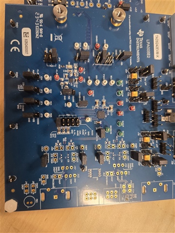
I'm currently evaluating the TAD5242EVM-K and have connected an external I2S source to the AC-MB board included in the evaluation kit.

My MD0–MD5 configuration is as follows:

  1. MD0 – Shorted to ground (I2S Target Mode)

  2. MD1, MD2 – Set to 2'b10

    • AVDD = 3.3V

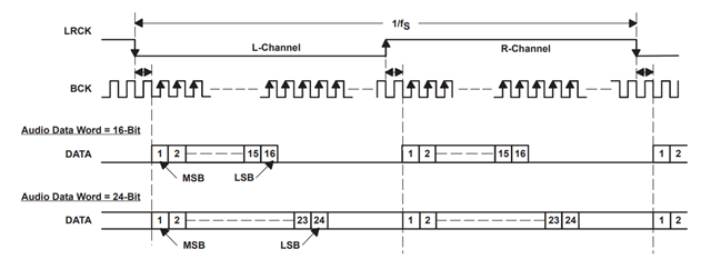
    • Word Length = 24-bit, Linear Phase

    • Decimation/Interpolation enabled

  3. MD3 – Set to 1'b0 (Quick Charge enabled)

  4. MD4, MD5 – Set to 2'b00 (DAC Diff LO – Highest Performance)

  5. MD6 – DOUT1 = jumper header to GND

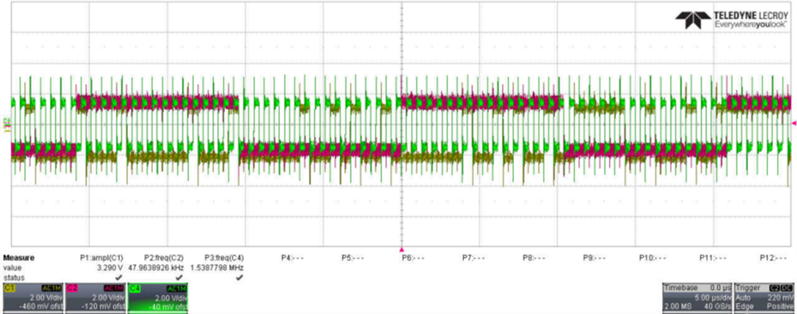
However, when I probe the output signals using an oscilloscope, I’m not seeing any signal from OUT1P and OUT1M test points. Additionally, OUT2P and OUT2M are producing identical waveforms, resulting in a flat line at 0 when using the math function. Moreover, the MD0-MD6 configuration settings on the TAD5242EVM-K user guide is different from the ones on the TAD5242 datasheet. 

I have also taken a look at  TAD5242EVM-K: Only one channel has sound. . I have checked over and over again, but I kept getting the same result

Is there a configuration step I might be missing? Would you be able to share the correct jumper header settings for the board, or confirm if this setup works on your end?

Thanks in advance for your support.

Best Regards

Ena

  • Hi Ena, 

    did you test it in the  configuration as shown in the reference post?


    Also can you confirm you have verified the I2S on the board and everything is in order? ( Please send me a screen shot of all the I2S signals on one screen so I can monitor the clks as well as the edges and etc,)

    Lets get it to work for a known configuration and then we can modify it for other configurations.

    Regards,

    Arash

  • Hi Arash,

    Attached are the I²S waveforms captured via oscilloscope.

    • Yellow signal: SD

    • Red signal: LRCLK, operating at a sampling rate of 48kHz

    • Green signal: BCLK, running at 1.5MHz

    Appreciate your assistance!

    Best Regards,

    Ena

  • Hi Ena,

    for 24Bit the BCK has to be 2.304E+06  and for 32bit BCK  has to be 3.072E+06.

    The I2S clks have to be very accurate and also the format (LJ or I2s or TDM) of input has to match with the set up for device ( for I2S the edges has to match the following figure) 

    I could not see the edges of SDIN ( yellow) . Your clks are really noisy , specially LRCLK, but helped me to  count 16 cycle of BCK , not 24 as you intended. 

    Please use this equation to make sure your set up is correct.

    BCLK= # of Ch.  *  Ch depth  * Fs

    I close this post as it seems the issue is I2S set up and with above guidance you should be able to resolve it.

    Regards,

    Arash