Other Parts Discussed in Thread: PCM5100
Tool/software:
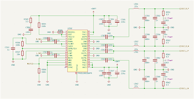
I designed a Digital Audio circuit with the TPA3118D2 as the audio amplifier.
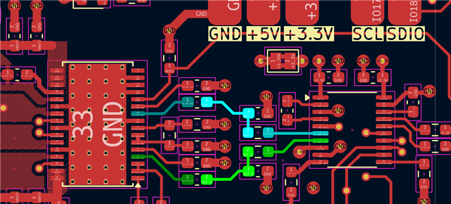
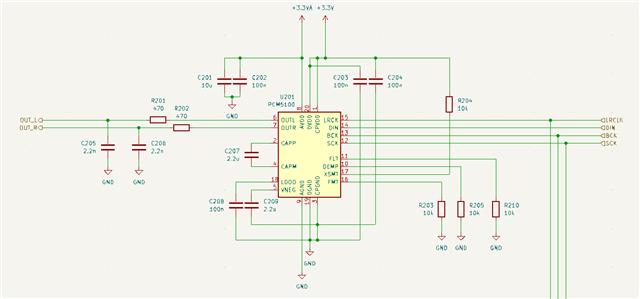
It's using a PCM5100 as a I2S DAC which is connected to the TPA3118. I've attached the parts of the schematics to see the design.
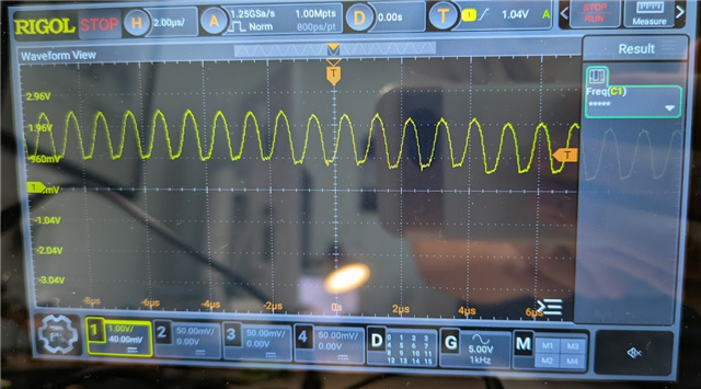
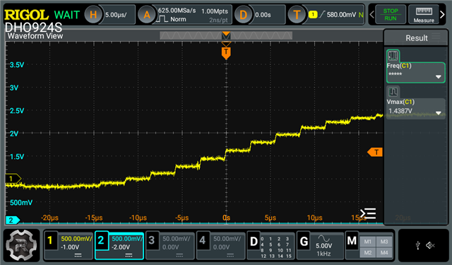
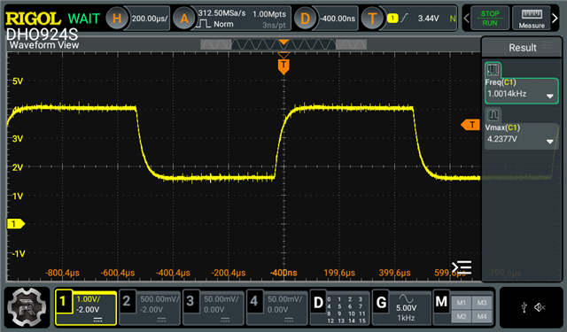
Generally I can hear sound output but it has a lot of noise. When checking the audio inputs with a scope I can see a ~1MHz sine wave modulated on the input channel.
Scope picture shows measurement directly at the TPA3118 pin.
I tried disconnecting the DAC output and the output signal is very nice following the I2S data, meaning the 1MHz is coming from the TPA3118.
Interestingly this wave is only present to the inputs connecting to the DAC. The negative inputs RINN/LINN don't show the sine wave.
Anyone has an idea what this is and how to fix it?
The PCB was soldered in an oven and not by hand, so gnd connections should be solid.
PCM5100 SCH
TPA3118 SCH
Scope RINP