LM48100Q-Q1: Why am I getting noise on the LM48100Q audio amplifier, even from a flashing LED ?

Part Number: LM48100Q-Q1

Tool/software:

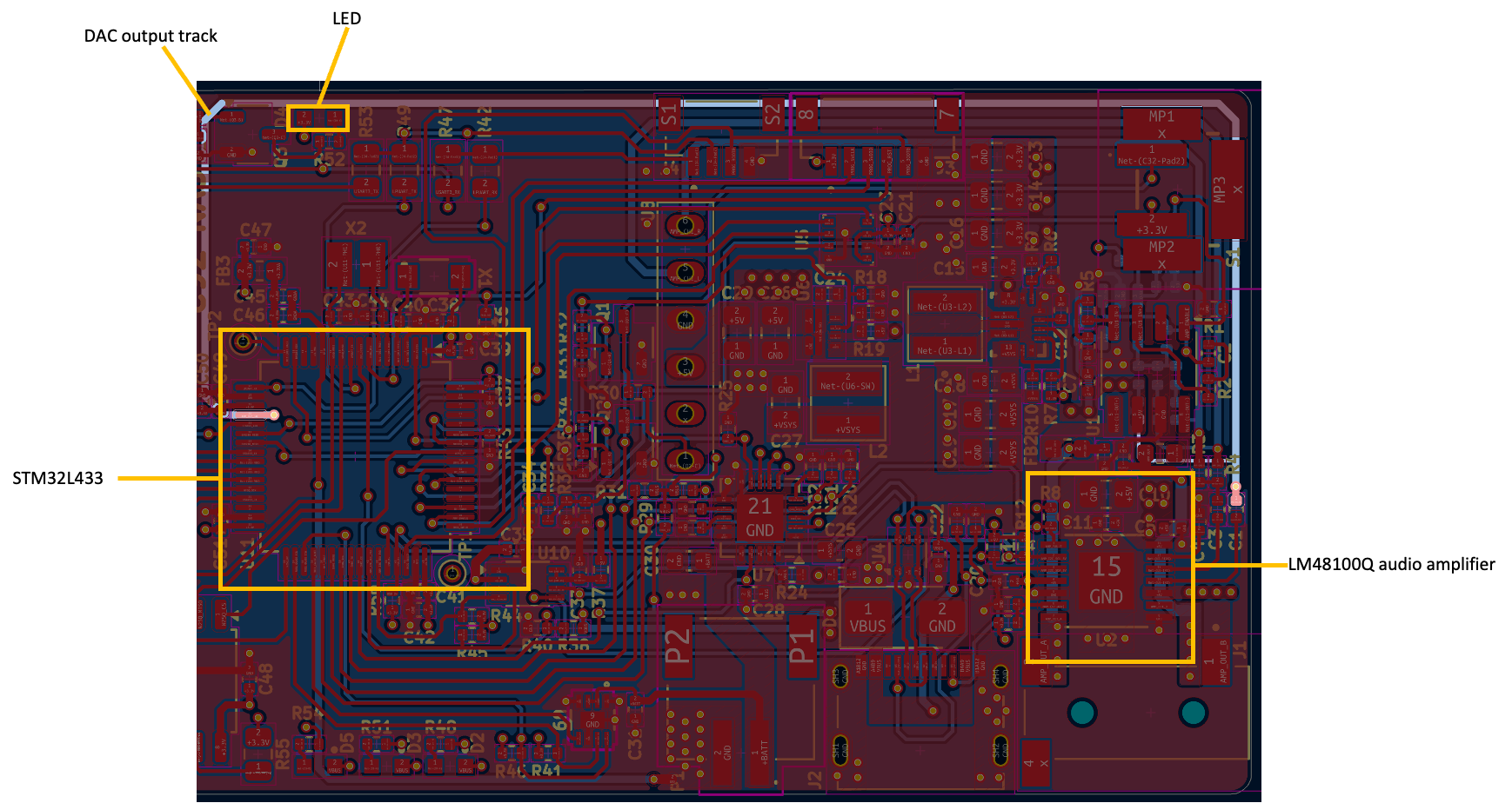
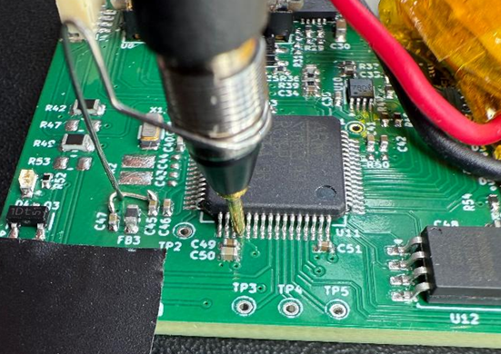
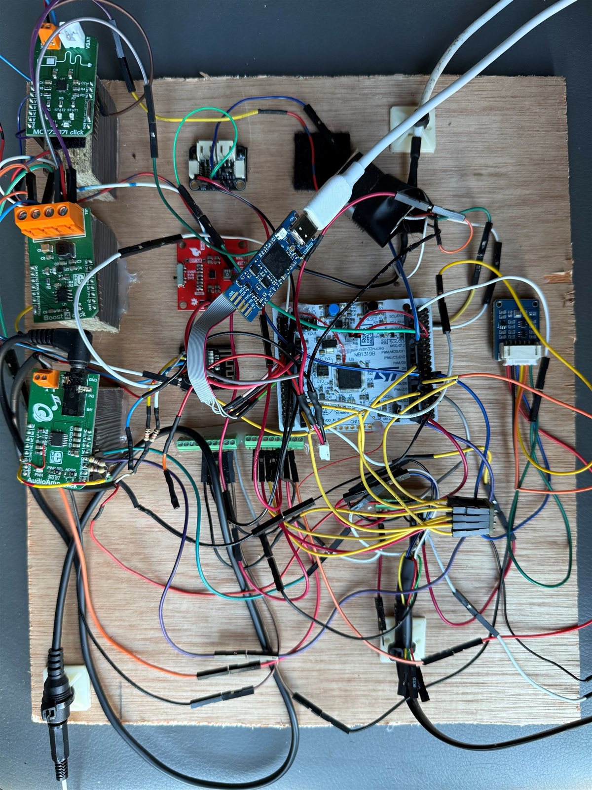
I have designed a custom PCB that uses the LM48100Q audio amplifier, but I am getting a hissing noise and interference from a flashing LED.

The link below shows a video of the hissing noise and the interference from the LED...

https://freeflyer.dynu.net/nextcloud/index.php/s/mA6gR8C5mc58f2D

If I disable the flashing LED, the hissing noise still remains but the interference from the LED stops...

https://freeflyer.dynu.net/nextcloud/index.php/s/pibfRrG9baA4TRj

How can I stop the hissing noise and interference from the flashing LED ?

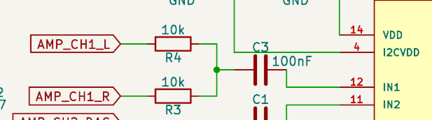
The schematic for the amplifier is below...


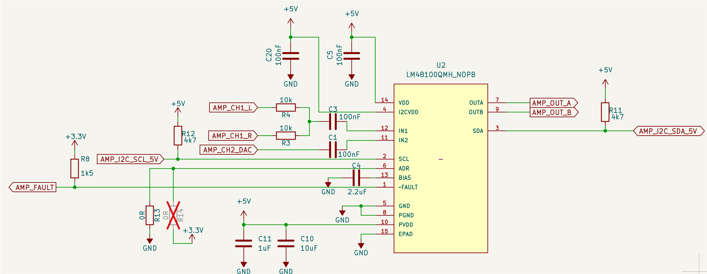
IN1 is disabled, only IN2 is enabled.

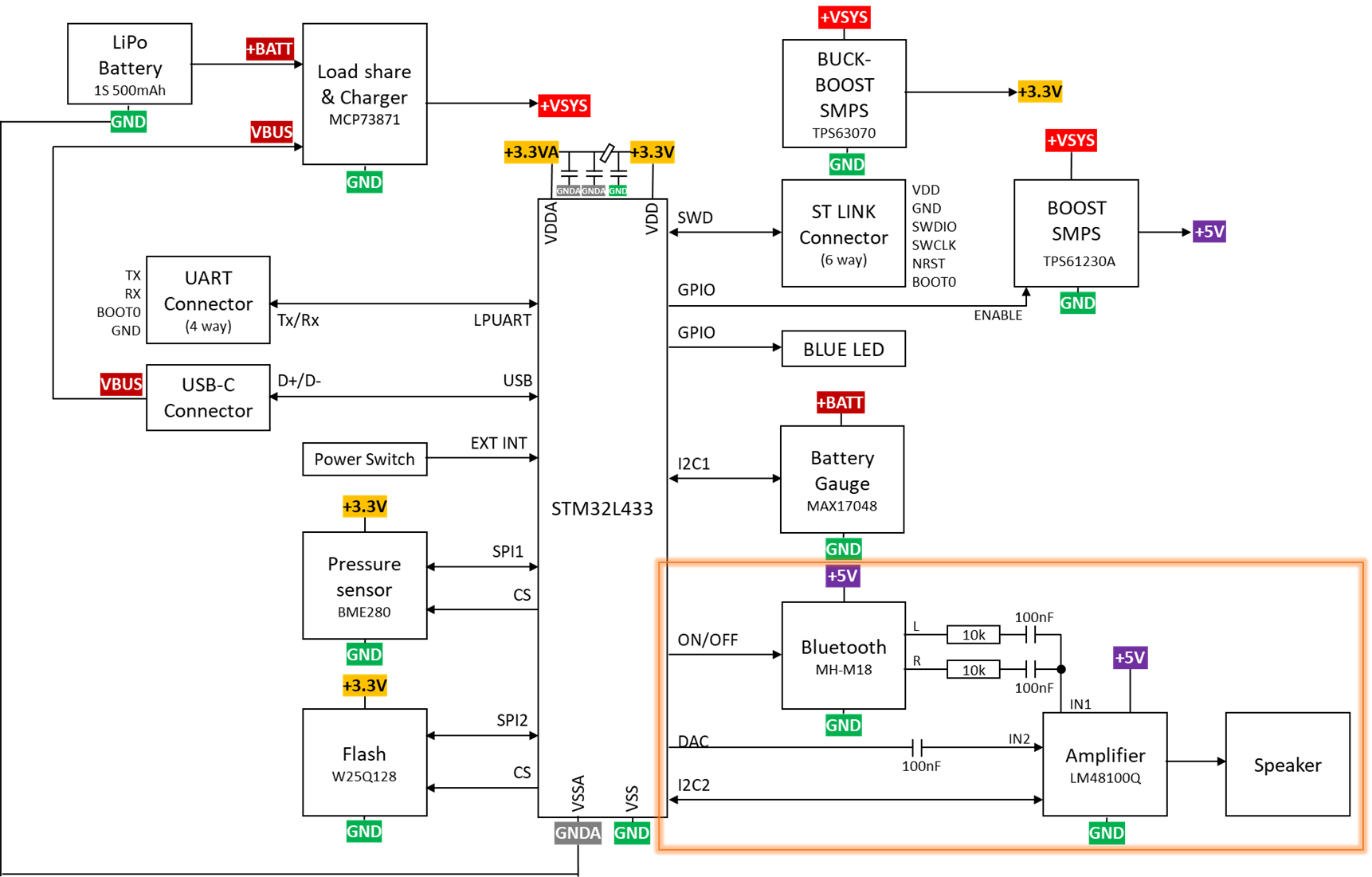
IN2 is connected to the DAC output of an STM32L4333 (which plays the audio voice prompts).

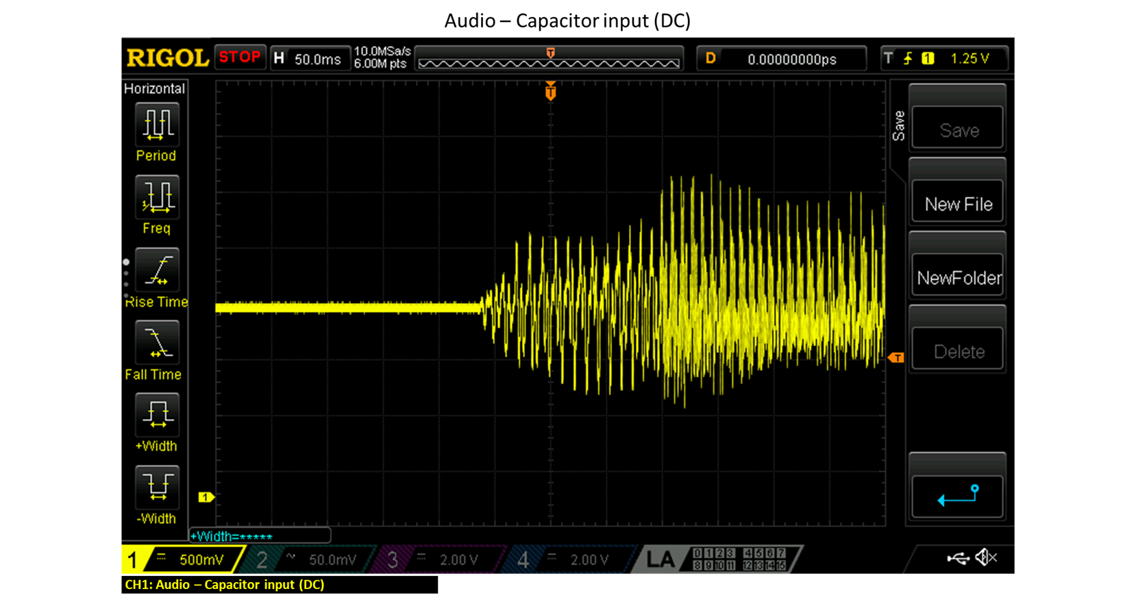
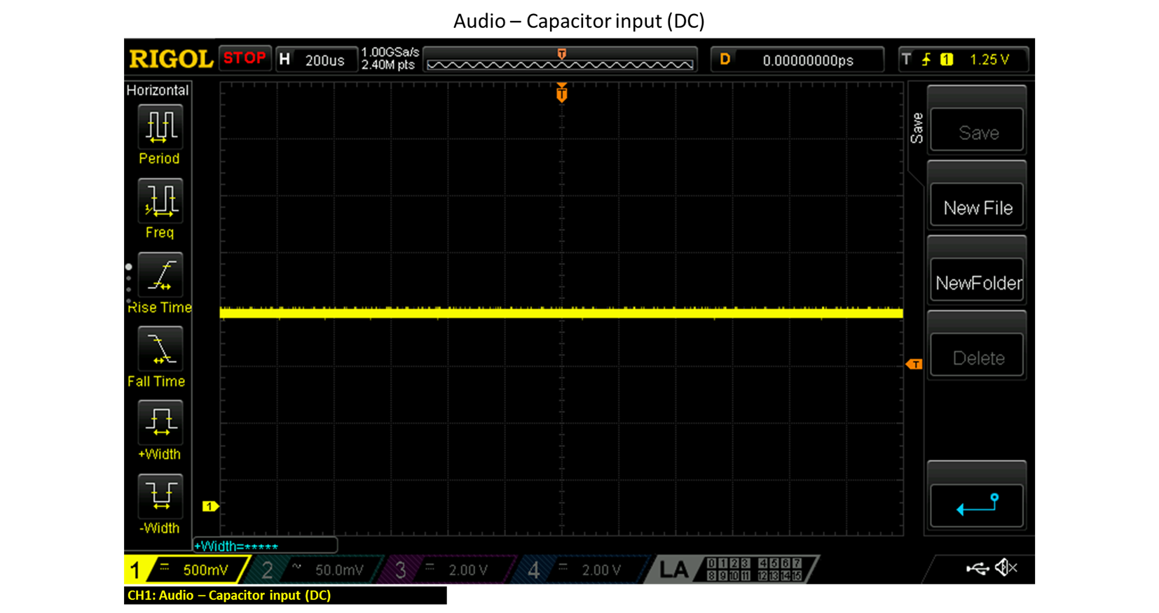
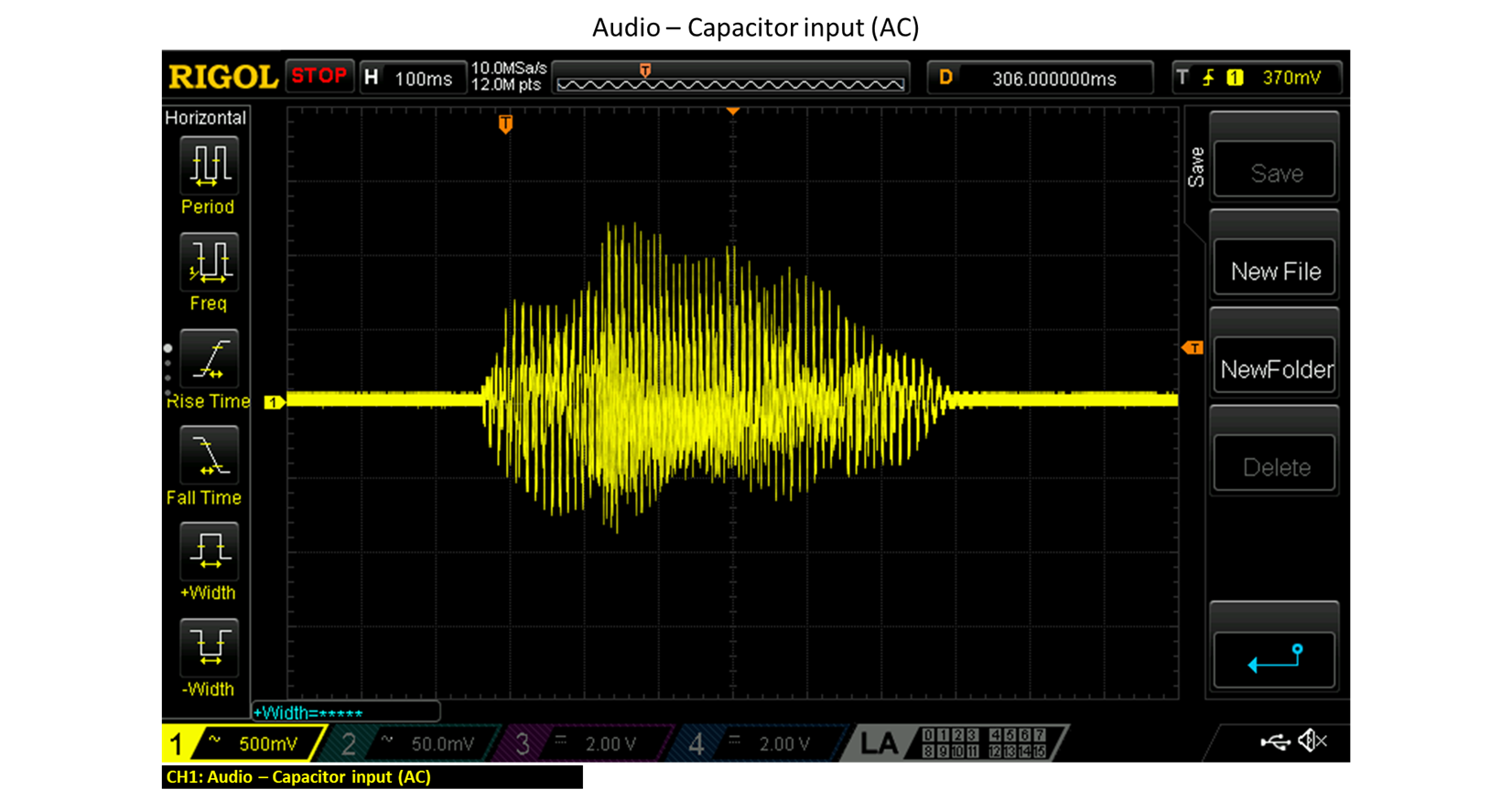
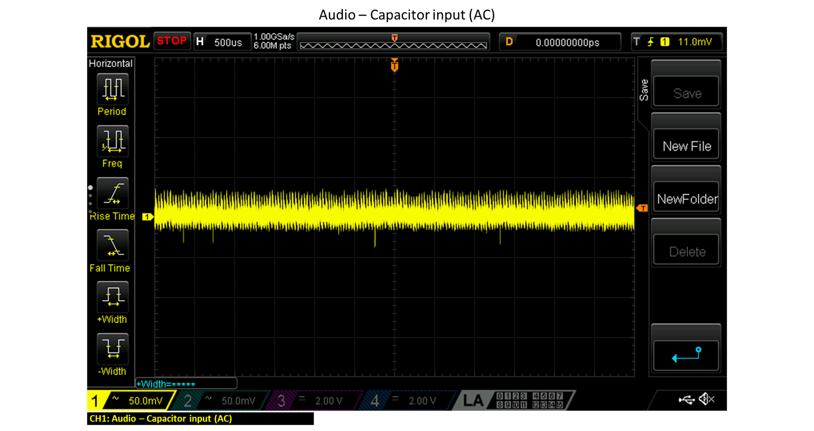
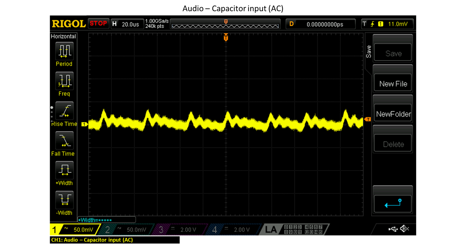
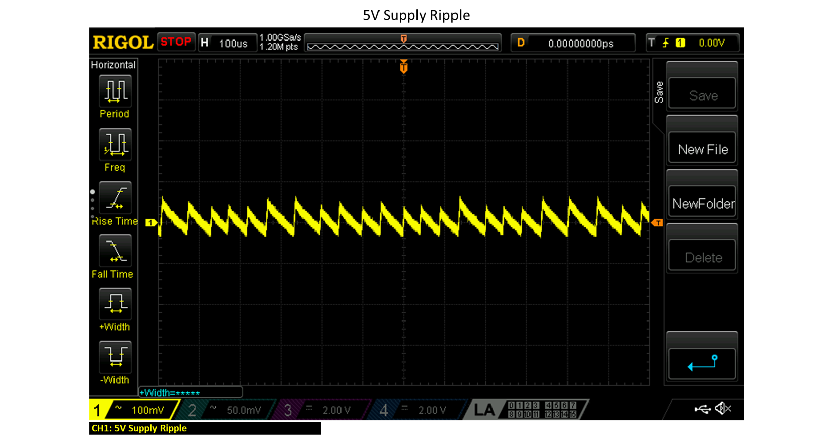
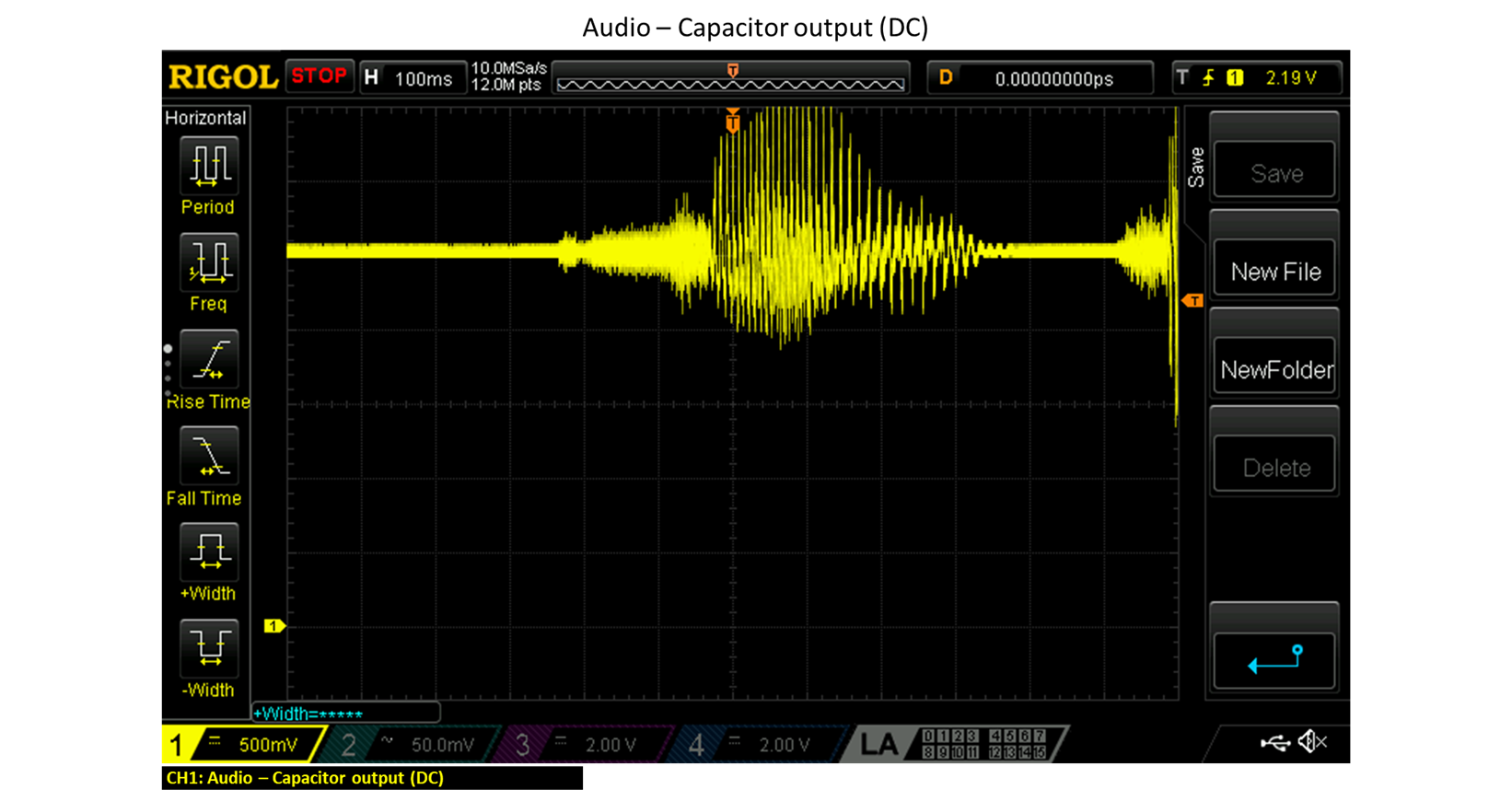
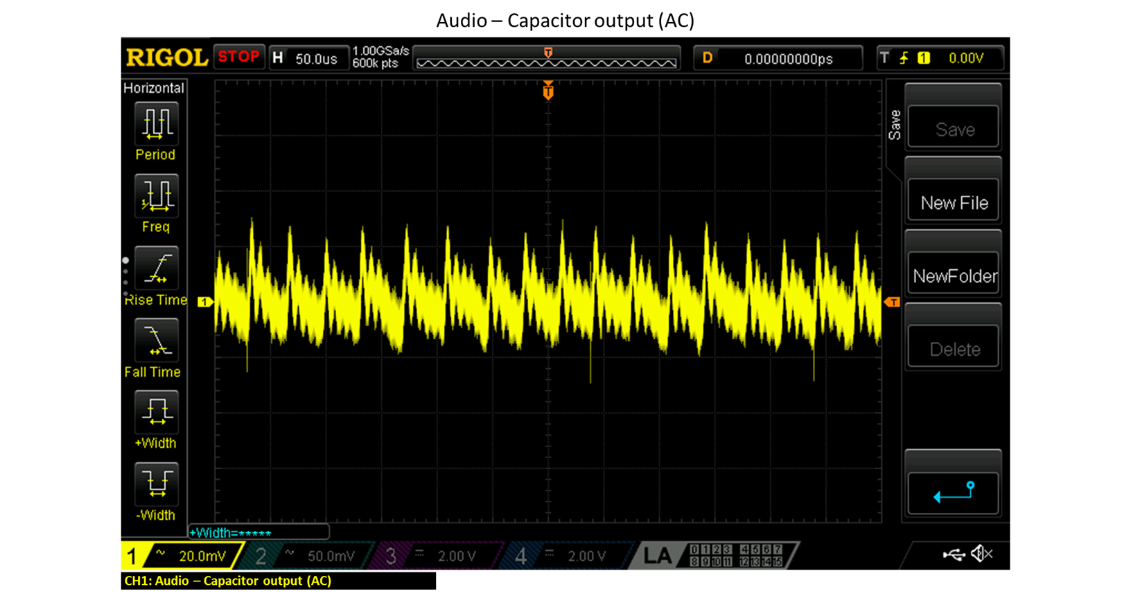
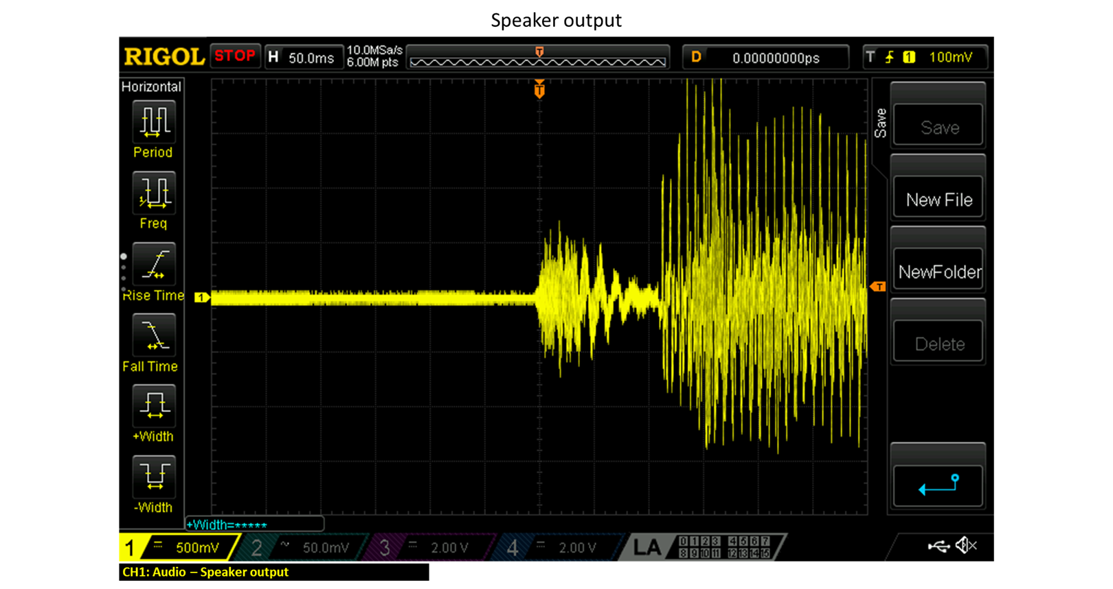
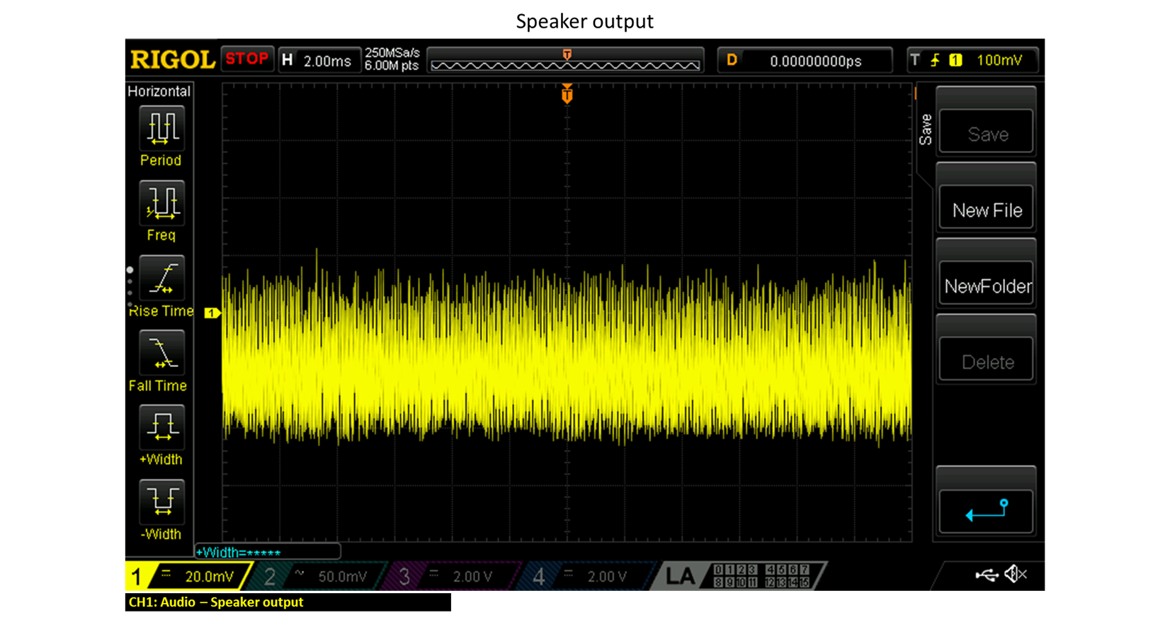
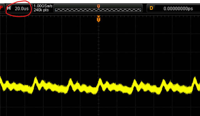
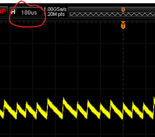
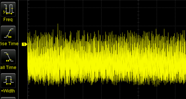
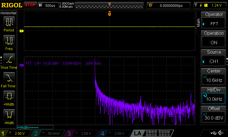
I have scoped the input and output capacitor (C1), the 5V supply and the speaker output, but I can't see the noise or LED interference.

The scope captures can be seen here...

https://www.dropbox.com/scl/fi/6j7q...ey=czaukal56ih5fx6if4ra5zc36&st=ha6wp8pu&dl=0


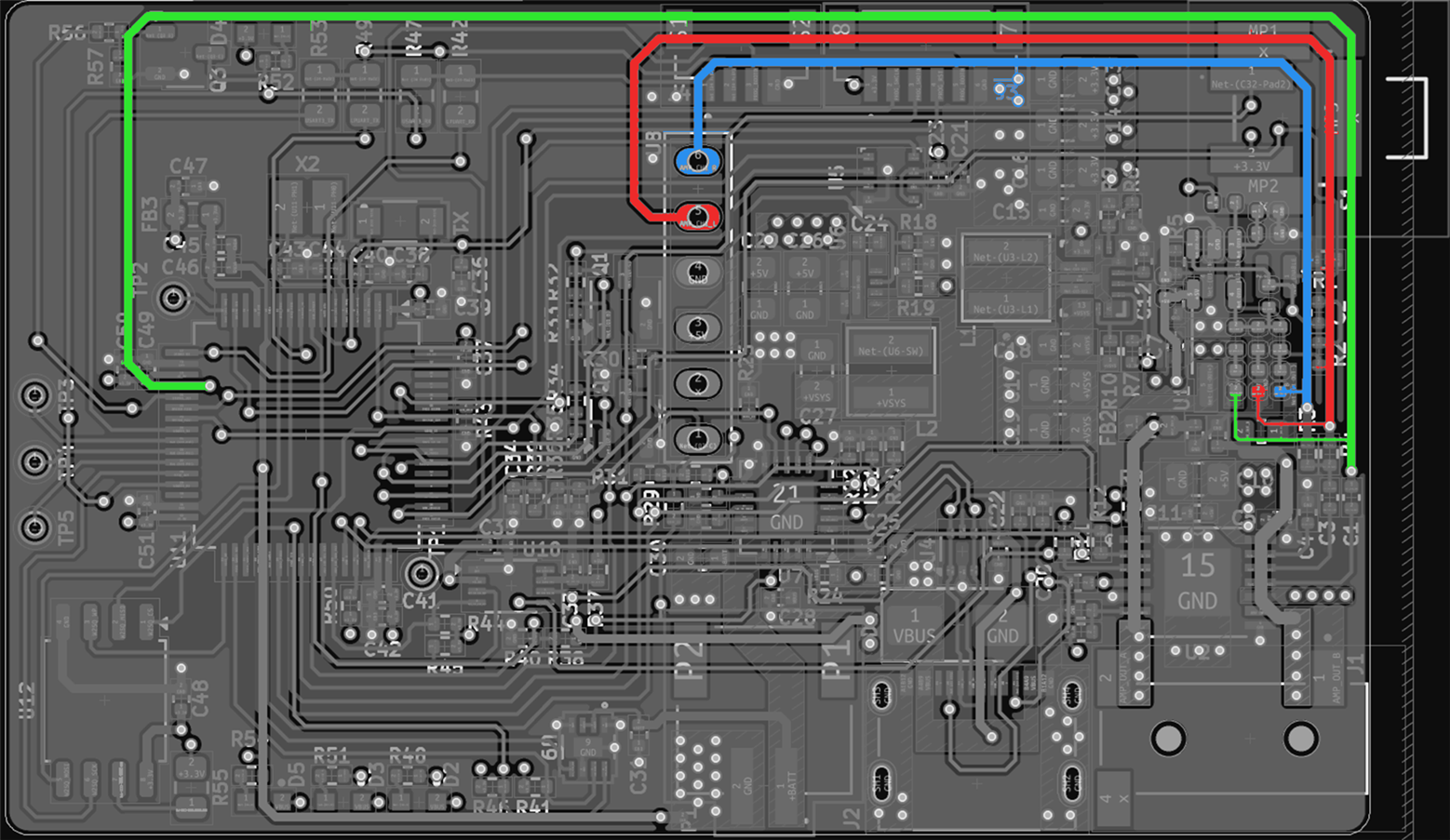
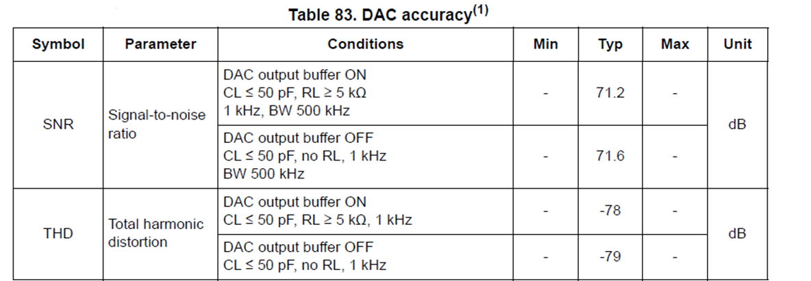
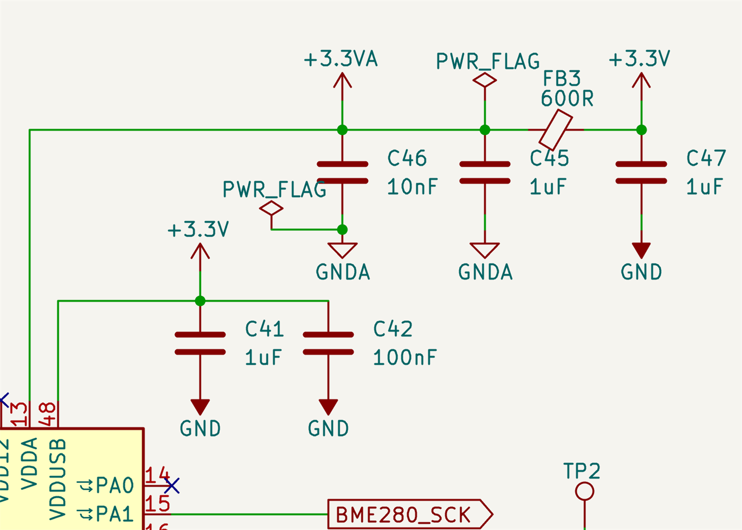
VDDA (pin 13) on the STM32L4333 for the DAC is filtered...


VSSA (pin 12) on the STM32L4333 for the DAC has a track to the battery negative pin...


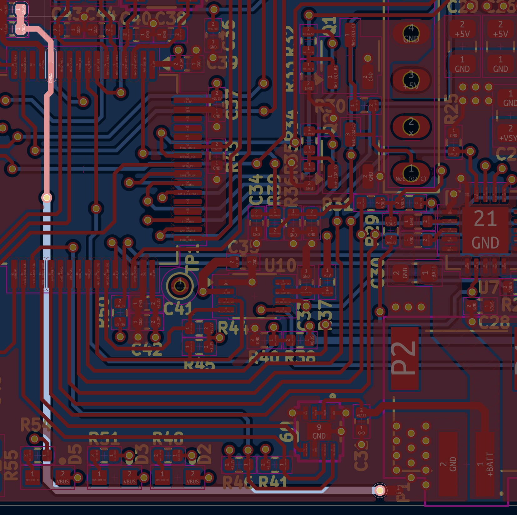
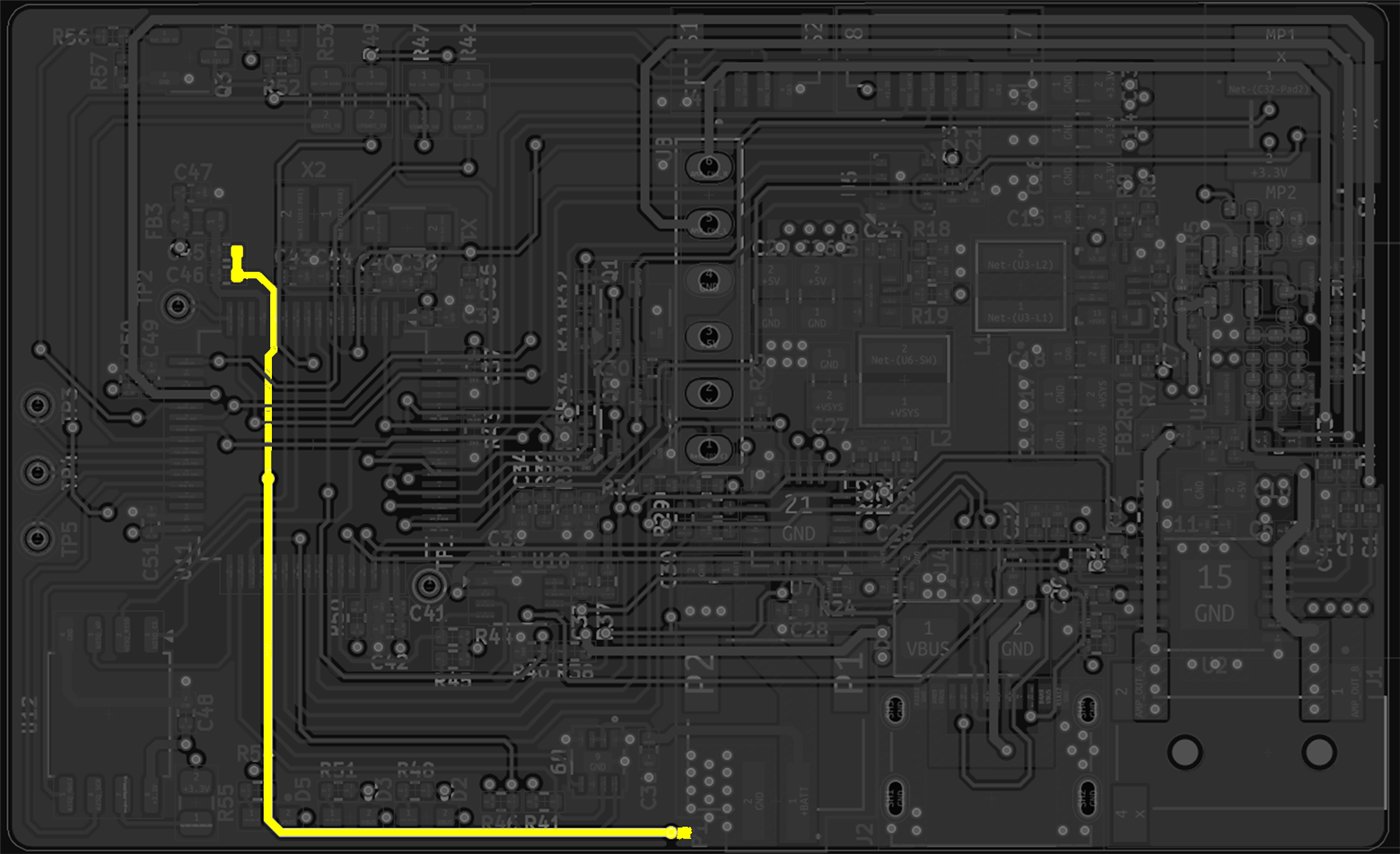
The DAC output track does run under the LED but I am suprised this causes interference....

  • Hi John

    Sorry that I can't open you link, IT blocked them.

    But from your schematic and layout, indeed possible coupling noise. Single end input using, the audio quality would be lower, and your input trace is indeed too long.

    And another thing possible could have a try. The R4/R3 resistor makes IN1 high impedance. This 2 resistor seems quite close to LM48100. Have a try to remove this 2 resistor, and short the resistor place to GND. Possibly would make the results better.

  • Thanks Shadow He,

    The noise is on channel IN2, not channel IN1.

    Channel IN2 is connected to the DAC output of the STM32

    Channel IN1 is connected to the DAC output (left and right) of a bluetooth audio receiver MH-M18 but this is temporarily disabled.

    See block diagram below (bottom right)...

    The links that you are unable to view show videos of the audible noise on channel IN2 (from the STM32 DAC) whilst channel IN1 is disabled.

    Strangely, I don't get noise on channel IN1 when it is enabled, even though the bluetooth receiver DAC channels tracks are routed similar to the STM32 DAC for channel IN2.

    Below are the scope captures of amp channel IN2, but I can't see any noise for the hiss or interference from the LED....

  • The PCB track routing is shown below:

    Green is the STM32 DAC output

    Red is the bluetooth receiver DAC right output

    Blue is the bluetooth receiver DAC left output

    The analogue ground (GNDA) for the STM32 DAC is shown in yellow below, it goes back to the battery negative terminal...

  • I have uploaded the videos (from the links) - see below...

  • Hi John

    A little strange, that the waveform you captured at input line, seems not match the noise.

    In your video, the LED is switching at around 10Hz? Or maybe a little higher. 

    But the input waveform, the noise frequency is more likely to be 25KHz. It is quite similar to the noise on the 5V power supply, maybe you could double check on this point. And 25KHz itself is not able to be heard.

    And your output waveform shows, not a very clear fixed frequency on it, more seems to be white noise. You could try to do FFT analysis about it to see more clearly, any fundamental frequency could be find out from this waveform. And is below waveform captured with led working?

    My guessing for now, is the noise mainly conducted through GND plane, as both your power supply and input has similar frequency. And led circuit seems raised the background noise level, make it more clearly heard from speaker.

  • Thanks Shadow,

    The waveforms captured were with the LED flashing.

    I finally got round to measuring the FFT of the STM32 DAC output, but it does not mean much to me...

    The measurement was taken at the STM32 DAC output pin and a local ground....

  • Hi John

    FFT looks quite clean, not having a special noise peak, just a DC. 

    But the back ground noise level seems too high, in your FFT analysis, around -50dBV, which is 3mV. For the audio side, 50uV~100uV white noise, already possibly been heard from some sensitive speakers. 3mV is enough to generate clear sound. 

    MCU's internal DAC usually not specially designed for audio, and possibly have this background noise level. You could check the spec of STM32. 

  • Thanks Shadow

    Which parameters are required for the STM32 DAC ?  Below is the SNR and THD...

    Strangely, when I built the prototype using development boards, I don't get the same hiss that I do with my custom PCB which is surprising given the rats nest of wires...

  • Hi John

    Which parameters are required for the STM32 DAC ?  Below is the SNR and THD...

    SNR -71.4dB. If using 3V as their DAC peak output voltage, it's around 0.5mV rms noise level. Better than your board. 

    There possibly some other noise source on your board, and raised the whole back ground noise. Like some DCDC power supply?

    Try shutdown all of other circuit, and maybe provide external power supply, only leave STM32 and LM48100 working, see if able to get better results.