


Other Parts Discussed in Thread: TAS5713
Tool/software:
Hello,
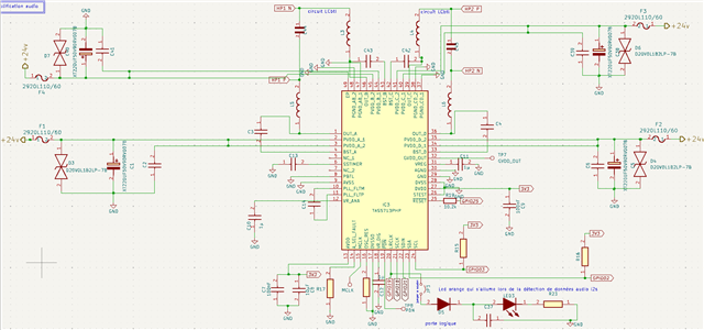
We are currently designing an audio amplifier board using TAS5713PHP (2-channel digital input Class-D).
Application context:
-
Power: ~2×10 W into 6 Ω loudspeakers
-
Supply: PVDD = 24 V
-
Inputs: Raspberry Pi 4 I²S (BCLK = GPIO18, LRCLK = GPIO19, DIN = GPIO21)
-
No MCLK line available → we rely on TAS5713 internal PLL for clocking
-
Control: I²C at 0x1A on bus
i2c-1 -
ALSA driver: snd_soc_tas5713 (Linux 6.x, RPi4)
Questions:
-
Schematic check: do you see any issue in our design (supplies, reset, I²S wiring, I²C pull-ups, BTL outputs, etc.)?
-
No MCLK mode: datasheet says “Operational without MCLK” with PLL – can you confirm this mode is officially supported and stable at 48 kHz fs?
-
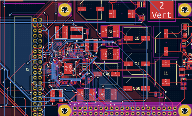
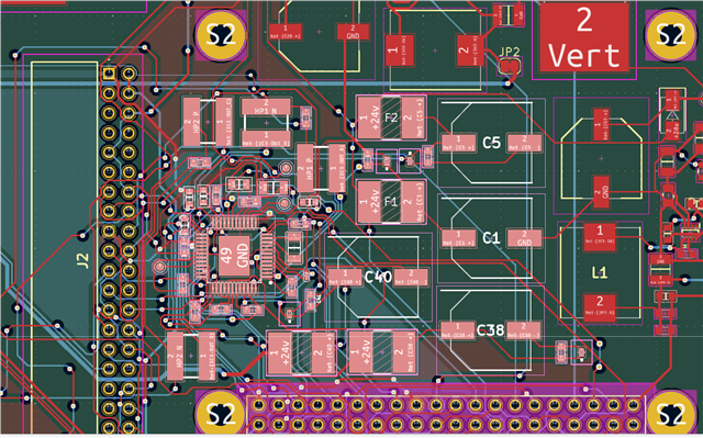
Layout recommendations:
-
PVDD decoupling (bulk + ceramics placement)
-
Pad thermal vias and ground return
-
Output stage routing for EMI (ferrites/snubber needed?)
-
-
Any known errata or register setup required when using PLL/no MCLK mode?
Attached:
-
Schematic (only TAS5713 section, I²S + I²C)
- PCB (top and bottom parts)
Thank you very much for your feedback.
Best regards,
Links: