This thread has been locked.

If you have a related question, please click the "Ask a related question" button in the top right corner. The newly created question will be automatically linked to this question.

TPA3110 start up voltage (UVLO?)

Other Parts Discussed in Thread: TPA3110D2

Hi.

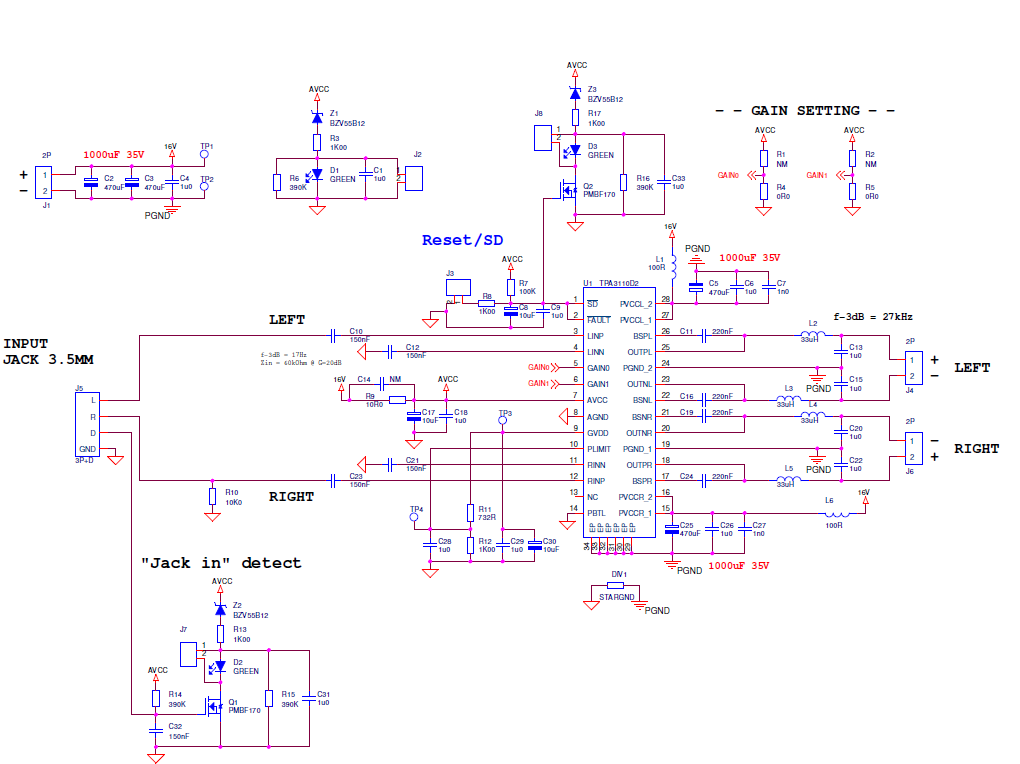
I'm using the TPA3110 for a 2x15W amplifier for my boombox. The datasheet states operating voltage from 8-26V. I'm unable to startup the circuit if the voltage is below 13,3-13,5V.. I can't find any information regarding UVLO in the datasheet. When the amplifier is turned on (above 13,5V input), the input can be reduced to 8V before it turns off.

Kind regards
CWilson.

  • The schematic:

    The 3 zeners (12V) are removed (12V+Vf_LED ~13,5V). I thought it was them which made the trouble, but they aren't.

    C8, C17 and C30 is removed.

  • Hi, CWilson. Thanks for using the TPA3110D2 in your boom box!

    The power-on threshold voltage for the TPA3110D2 should be around 8 V, not far off from what you're seeing for the power-off threshold.

    As you increase your supply voltage (the "16V" in your schematic), is the value shown on your power supply equal to the value measured directly at the PVCCL, PVCCR, and AVCC pins? If not, I bet something is drawing current as you ramp up the supply, keeping the amp from reaching the supply it needs. Are you able to put your supply to, say, 13 V, and see 13 V directly at the power pins of the chip and still not see the amp turn on?

    What happens when you remove Q2 and try to ramp the supply? Do you see the amp turn on at a lower voltage?

    Best Regards,
    Matt

  • Hi Matt,

    I measured the voltage the 3 places and it's 10.068, 10.068 and 10.053V (AVCC).
    I moved the upper SD-resistor (100k) directly to PVDD (16V) instead of after the 10R (AVCC). This didn't help.

    I removed the resistor R12 (lower resistor in PLIMT network). Now the AMP starts at  8V (or even a little bit lower).
    The PLIMT network draw 4mA, which was too much (7V/(732R+1000R) = 4mA.
    Now I don't have PLIMIT, which is OK because the IC will shut down if it gets too warm :-)

    /CWilson.
     

  • Hi, CWilson. Good catch on R12! Nice board sleuth work! You are correct that GVDD will have too much of a current pull on it with that resistor divider. Anything more than 2 mA can mess up the output FET gate drivers, which I bet is why you weren't seeing the amp start up.

    If you want to keep using PLIMIT (a good idea), you could always scale up your resistors R11 and R12 by a factor of 100. That would reduce the pull on GVDD and keep your chip starting up when it should. The PLIMIT pin cares about the voltage it sees, and as long as the resistor divider provides the same voltage as your old 732 Ω+1 kΩ case, you should have the same PLIMIT effects.

    Best Regards,
    Matt

  • Hi Matt,

    I simply forgot to scale up the resistor divider network - it should have been 7320k and 10k, not 732R/1000R.. By multiplying by 100, won't the pin be too noise sensitive?

    What is the main reason for using the PLIMT? As I can see in the datasheet on page 17, the output looks like it's clipping, which is bad for your speakers? Also a deep bass will be limited...? 

    1) I have a question regarding the datasheet: 

    Page  17: "VP is the peak amplitude of the output possible within the supply rail." So is that supply voltage or? It's not specified what VP is.

    Let's say:

    RL = 8R, Rs = 0R3 and PLIM is 4V (-> VP = 4*4).

    Then the resulting power limit is 13,84W. But VP is now 16V - does it mean that I have to supply my amplifier with 16V in order to get 13,84W out? Otherwise I have to raise PLIMT for lower voltages to compensate?

    2) I assume I just can add a small heat sink to lower the temperature. In that way I won't stress the component? And thereby set my PLIMT to GVDD (7V) without any risk of failure to my AMP or speakers.

    /CWilson

  • Hi, CWilson. You could also multiply by 10. That would limit the current drawn on GVDD to a reasonable level.

    We introduced PLIMIT as a form of speaker protection and chip protection. It was marketed as "SpeakerGuard". The output is effectively soft-clipping with PLIMIT active, kind of like vacuum tube distortion. PLIMIT sets a virtual supply rail where the output voltage swing cannot exceed that virtual supply. Using P = V²/R, you can choose a virtual supply rail to not exceed a maximum power rating for speakers. Clipping isn't great for speakers, but blowing out the speakers is worse. PLIMIT is more a safety feature than a sound enhancer, although I've worked with someone who wanted PLIMIT distortion intentionally! (A fan of old vacuum tube amp crunchiness.) If you're not concerned about damaging your speakers in the peak output powers you plan to use, I would avoid PLIMIT.

    Regarding your questions:

    1. VP is that virtual supply rail I was mentioning above. It is necessarily less than or equal to the supply rail. For your example, you would need such a supply to get that output power, yes, but the output would be PLIMIT clipped. If there is no risk of damaging your speakers at 13.48 W, avoid PLIMIT altogether and get more power out of a smaller supply rail (coming back to P = V²/R).
    2. You could add a heat sink to lower the temperature for protection. We offer the PLIMIT protection for people who are making cost-sensitive electronics, and heat sinks can get darned expensive. If that doesn't bother you, PLIMIT set to GVDD and a heat sink for protection will work just fine. I recommend to most people that they keep PLIMIT set to GVDD unless they have a reason to limit the power.

    Best Regards,
    Matt

  • I Matt,

    Vin = 12V and RL = 8R. So the max power is 12*12/8 = 18W rms..? My input is set to 1Vrms and the gain is 20dB, which means the output voltage is maximum 10Vrms = 12,5W (10V^2/8R).

    The speaker can each handle 60W peak and 30W rms. http://www.monacor.dk/produkter/hoejttalerenheder-hifi4-5/vnr/100920/ so this shouldn't be a problem.
    I'm adding a small heat sink: http://www.farnell.com/datasheets/809516.pdf with Rth of 26,3 C/W.
    I think the only problem for me is the heat dissipation in the coil of the speaker since the cabinet is closed box :-)

    Do you have a recommendation of how many uF/W (for each channel) I need for 12Wrms power?
    I'm supplying from a 12V battery source with 2x1000uF for each L and R channel (will be upgraded to 2x3300uF on Monday). I'm thinking of adding 2x10mF which L/R shares while they still have the 2x3300uF each. 
    I'm adding the capacitance in hope of getting more bass. 

    /CWilson.

  • Hi, CWilson. Looks like you're in the clear for headroom, both in your output power and speaker dynamics. Your math checks out.

    I've seen some designs around the TPA3110D2 and related parts with power rail capacitors out the door. More capacitance doesn't usually hurt. Part of my job is reducing the number of caps on a board if possible, for cost savings. That doesn't seem to be an issue for you. The part will work just fine for 12 Vrms with the baseline power capacitors on the TPA3110D2 EVM. I've attached its schematic here for your review. 7635.TPA3110D2 EVM Schematic.pdf

    Do you think you're all set here, CWilson? I think we've covered everything. Please let me know how else I can help.

    Best Regards,
    Matt

  • Thank you for your help.

    I think I'm fully covered now.

    /CWilson