This thread has been locked.

If you have a related question, please click the "Ask a related question" button in the top right corner. The newly created question will be automatically linked to this question.

Why does duty cycle of LRCK is still 50% in PCM1865?And no output in DOUT pin?

Other Parts Discussed in Thread: PCM1865, TMS320DM8168

Hi,TIer.

I use PCM1865 to capture FOUR channel mono audio to TI's soc dm8168 via TDM mode, and pcm1865 acts as master.

I use our DM8168 custom board and PCM1865 EVM to test. I install a 24.575M osc into the PCM1865 EVM.

And wired the +5V,GND,SCL,SDA from our 8168 board to PCM1865 EVM.

After Power on the 8168 board and PCM1865 EVM.

I write the following data to 1865's register, and I2C write operation is successful for I have read back the corresponding register.(All operation is on page0)

--------------------------------------------------------

data                register

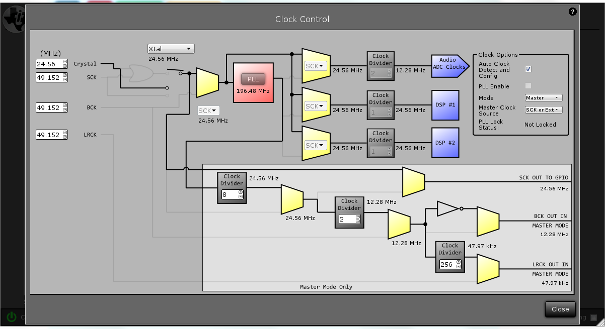
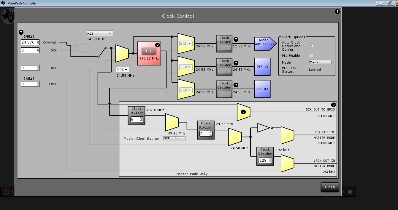
0x1f                  0x0b                    //16bit PCM, TDM/DSP mode,1/256 duty cycle of LRCK.

0x10                 0x20                   //Master,without auto clock detect.Use 

0x01                 0x21                   //DSP1 divider:1/2             12.288M

0x01                 0x22                   //DSP2 divider:1/2            12.288M

0x03                 0x23                   //ADC clock divier:1/4      6.144M

0x01                 0x26                   //SCK to BCK:1/2               12.288M  256FS

0xff                    0x27                   //BCK to LRCK:1/256        48K sample rate

0x00                  0x28                   //disable PLL

--------------------------------------------------------

I do NOT use PLL. And test in 48K sample rate.

I have checked the status register, power,clock,etc.There is no error.

And I have measured the frequency of LRCK, and BCK. BCK is 12.288M.LRCK is 48K. But according to the spec, in TDM mode,the duty cyclone should be 1/256.But when I measured, it is still 50% duty cycle.What may cause it?

And there is no OUTPUT on DOUT pin.

Expecting for any reply.

BR!

  • HI,I have debug it again.
    Now ,after I write the corresponding register, and read register 0x72, it returns 0x03, indicates PCM1865 is standby.
    However, register 0x70's value is 0x70,means it is in RUN status.

    And according to the datasheet, if the clock configure is error, the PCM1865 is in standby status. But the register 0x75 and 0x78 indicates that both the clock and power status is right.

    Why PCM1865 is still in STANDBY status?

    I use PCM1865 EVM from TI.
  • Hi SuitJune,

    As for your register settings, I see one thing that could be causing this. If you want the part in master mode you must set the MST_MODE bit in register 0x20. This would be a value of 0x30 written into register 0x20. If in slave mode and not receiving any clocks, the part will be in standby mode.

    Justin
  • I will also be testing this myself in the near future and will be able to give you a detailed setup for TDM. We will then be adding information the data sheet about TDM mode.

    Justin
  • MST_MODE bit is Bit4 in register 0x20.
    So, I think it should be 0x10,not 0x30.

    Yesterday I have a new test,I found that if I first configure the clock divider, thus making BCK:LRCK=256, then I set the PCM1865 TDM mode,and master mode. And the PCM1865 will be in RUN status. If I do NOT configure the clock divider first,then the PCM1865 will be in standby status.
  • Could I use PCM1865 to capture four channel mono audio using a single DOUT pin through I2S mode?not TDM mode.
    It seems that DM8168 can also receive multi channel audio with I2S mode.
  • HI,The above picture is TDM mode.The yellow one is DOUT, the green one is LRCK.

    The parameter is as follows:

    a.PCM1865 as a Master

    b.48K sample rate

    c.four channel capture

    d.TDM mode

    However, even if I set the duty cycle of LRCK is 1/256, it is still 50%.And there is no output on DOUT.

    This one is I2S mode,The yellow one is DOUT, the green one is LRCK.

    The parameter is as follows:

    a.PCM1865 as a Master

    b.48K sample rate

    c.four channel capture

    d.I2S mode

    However, there is only TWO channel input is effective. When I insert a audio jack into 1R or 1L,the signal will change as the picture shows, BUT if I insert the same jack into 2R or 2L,there is no response on DOUT pin.It seems that this is only a TWO channel capture.However, the device I use is PCM1865, and register 0x71 is 0x10, indicates that it is four channel capture.

    Expecting for your reply! I am so hurry to get it work!Thank you very much!!

    And I paste the write script for the PCM1865

    The format of script

    i2cset -f -y 1 0x4c reg_addr reg_value 

    0x4c is the PCM8165's dev addr

    This is I2S script in linux

    #reset
    #i2cset -f -y 1 0x4c 0x00 0xff
    #sleep 1

    #return to page0
    #i2cset -f -y 1 0x4c 0x00 0x00
    #sleep 1

    #duty cycle of LRCK is 50%
    #16bit transfer
    i2cset -f -y 1 0x4c 0x0b 0xcc
    sleep 1

    #For test
    #24.576M XTAL is multiplies of 48K
    #PCM1865 is Master
    i2cset -f -y 1 0x4c 0x20 0x10
    sleep 1

    #DSP1 clock no divider 24.576M
    #DSP2 clock divider 1/2 12.288M
    #audio adc clock: clock divider 1/4 6.144M
    i2cset -f -y 1 0x4c 0x21 0x00
    sleep 1
    i2cset -f -y 1 0x4c 0x22 0x01
    sleep 1
    i2cset -f -y 1 0x4c 0x23 0x03
    sleep 1

    #1/8 BCLK 3.072M
    i2cset -f -y 1 0x4c 0x26 0x07 
    sleep 1

    #BCLK to LRCK 64
    #i2cset -f -y 1 0x4c 0x27 0x3f
    #sleep 1

    #diable the dll
    i2cset -f -y 1 0x4c 0x28 0x00
    sleep 1

    This is TDM script in linux

    #reset
    #i2cset -f -y 1 0x4c 0x00 0xff
    #sleep 1

    #return to page0
    #i2cset -f -y 1 0x4c 0x00 0x00
    #sleep 1


    #i2cset -f -y 1 0x4c 0x0b 0xcc
    #sleep 1

    #For test
    #24.576M XTAL is multiplies of 48K
    #PCM1865 is Master
    i2cset -f -y 1 0x4c 0x20 0x10
    sleep 1

    #DSP1 clock divider 1:1 24.576M
    #DSP2 clock divider 1/2 12.288M
    #audio adc clock: clock divider 1/4 6.144M
    i2cset -f -y 1 0x4c 0x21 0x00
    sleep 1
    i2cset -f -y 1 0x4c 0x22 0x01
    sleep 1
    i2cset -f -y 1 0x4c 0x23 0x03
    sleep 1

    #1/2 BCLK 12.288M
    i2cset -f -y 1 0x4c 0x26 0x01
    sleep 1

    #BCLK to LRCK 256
    i2cset -f -y 1 0x4c 0x27 0xff
    sleep 1

    #diable the dll
    i2cset -f -y 1 0x4c 0x28 0x00
    sleep 1

    #Set for TDM mode
    #set duty cycle of LRCK is 1/256
    i2cset -f -y 1 0x4c 0x0b 0x1f
    sleep 1

    #TDM:4 channel
    i2cset -f -y 1 0x4c 0x0c 0x01
    sleep 1

    #Set Offset in TDM mode
    #i2cset -f -y 1 0x4c 0x0d 0x3f
    sleep 1

  • HI,please any response?
  • HI, any response please?
    I have just begun another test and debug.
    And I found that if set PCM1865 to I2S mode,then DOUT pin can only output TWO channel MONO audio, for FOUR channel audio, the remaining two audio is output by DOUT2 pin.
    And for TDM mode, it seem that can output FOUR channel audio through DOUT pin according to the datasheet.
    But, if I run the TDM script in linux, the phenomenon is different, I mean the DOUT waveform is different everytime.But no matter what the waveform of DOUT is, there is no effective audio output like I2S. If set PCM1865 to I2S mode,I can see the effective output on DOUT or DOUT2 pin.

    Could you give me a Workable script for TDM and master mode?I am going crazy~~~~~
  • Hi SuitJune,

    I am still working on fully testing TDM mode and will respond when I have all my testing done and have confirmed the operation.

    Justin

  • HI SuitJune,

    So I was able to get TDM working in both master and slave mode. The salve mode could work with both 50% LRCK and 1/256 LRCK, however master mode only worked with 50% LRCK. Since what matters is the rising edge then this can still work.

    My procedure to get the EVMs working in TDM master mode:

    1. Plug in EVM USB

    2. Select mode 1, set jumpers, hit ok

    3. Set your clock dividers like the following:

    4. Next go to the Audio interface and set the Audio Format to TDM and select how many channels you want output.

    5. In this same menu you can change the TX offset or RX offset. 

    6. I was also able to get all 4 GPIO options outputting DOUT2 by setting the GPIO to output, then setting the second option to DOUT2, these pins were INT, MD6, MD5, and MD4. 

    7. Note that the 24 bit output for TDM will be 24 bits, without the 1 bit offset of I2S and there are no padding bits with each word. This means that each word is 24 bits exactly not 32 with 8 bits of padding like in I2S. The outputs will also be HIgh Z when not outputting a word so that other devices on the bus can drive the line.

    I hope this helps, if not please let me know what doesn't work.

    Justin

  • Thanks very much for your help!!!!!!!!!!!!

    My question:

    1. In your test, DOUT pin output four channel audio data??

    2.If PCM1865 is set to a Master in TDM mode,LRCK can only be 50%, then it is like even same to I2S mode? Right?

    3.But in my case, it seems that I can not read/write registers through PurePath. So,I use our TMS320DM8168 customer board and PCM1865 EVM, and wired them.

    And my clock setting is not same to you. I am in home now, and I am going to company to debug it right now.Could you please dump the register for all pages?Page0,Page1,Page3,Page253.

    Thanks very much again!!!!!!

  • Thanks very much.
    For master mode, if audio format is TDM. The duty cycle of LRCK has to be 50%, or else it won't work.

    Thank you.
  • 7. Note that the 24 bit output for TDM will be 24 bits, without the 1 bit offset of I2S and there are no padding bits with each word. This means that each word is 24 bits exactly not 32 with 8 bits of padding like in I2S. The outputs will also be HIgh Z when not outputting a word so that other devices on the bus can drive the line.

    ----Could we use 16bit output for TDM mode?I mean that for a mono audio sample,is 16bit.
  • Could you post a timing diagram for PCM1865 in TDM/master mode? Now we need to connect PCM1865 to our DSP TMS320DM8168, however, threre is a need for timing parameter in kernel driver:such as

    SND_SOC_DAIFMT_NB_NF:
    347 /* CLKRP Receive clock polarity,
    348 * 1 - sampled on rising edge of CLKR
    349 * valid on rising edge
    350 * CLKXP Transmit clock polarity,
    351 * 1 - clocked on falling edge of CLKX
    352 * valid on rising edge
    353 * FSRP Receive frame sync pol, 0 - active high
    354 * FSXP Transmit frame sync pol, 0 - active high
    355 */

    ,etc.
    So,expecting for a reply.
  • Hi SuitJune,

    I have recently came across a hidden register setting related to word length for TDM mode. It seems that the PCM186X device can operate TDM in 32 bit word length. If you set register 0x0B bits 2 and 3 to 00, this will enable 32 bit word length of 24 bit audio and 8 bits of padding. This will be changed in the data sheet on the next revision.

    Justin
  • thanks for your effective reply.

    And could we set for 32bit audio TDM transfer with 16bit audio data and 16bit padding?

  • Hi SuitJune,

    The padding cannot be changed per channel outside of the default resolution setting. (0 bits of padding for 16 bit, 20 bit, 24 bit, and 8 bits of padding for 32 bit)

    Justin
  • I met the same issue.

    PCM1865 master mode, TDM output format, set Page 0 Register 0x0B bit 4 (TDM_LRCK_MODE) to 1, the duty cycle of LRCK is still 50%, and what's worse, channels 5 ~ 8 output data are corrupted.

    As a reference, when Page 0 Register 0x0B bit 4 (TDM_LRCK_MODE) = 0, the waveform is correct.

  • Hi Xing,

    The PCM186X in master mode, LRCK can only operate in 50% duty cycle mode. However if you want a use a system that wants a 1 bit pulse, they usually only care about the rising edge, so the 50% duty cycle can still work. So when the PCM186X is the master in master mode you must use the 50% LRCK mode.

    Justin
  • Thanks. For TDM output format, I always set Page 0 Register 0x0B bit 4 (TDM_LRCK_MODE) = 0 in the device driver.
  • "This will be changed in the data sheet on the next revision."
    Hm, I have a lot off problems, before I found it.....
  • Hi Justin Bohr,

    Thank you for your Information on TDM4. It has been very useful for  1/256 ratio.

    But our requirement is 1/128 ratio. when I config for this ratio data is not coming out.

    Is there any possibility for getting 1/128 ratio?

    Please Help Me.

    Thanks & Regards

    Vamsikrishna