This thread has been locked.

If you have a related question, please click the "Ask a related question" button in the top right corner. The newly created question will be automatically linked to this question.

TLV320AIC10——FS and control register 2

Other Parts Discussed in Thread: TLV320AIC10, TMS320F2812

Hi,

In the Data Manual of TLV320AIC10,Fs = Sampling (conversion) frequency = MCLK/(256 × N), N = 1, 2..., 32。The value of N is defined in control register 2。In my application,MCLK is 2.048MHz,control register 2 is 0x0404,so the value of N is 4,then the test value of Fs is 8000Hz.But according to the formula,Fs = 2048000/(256×4) = 2000Hz.It do not conform to the test values.Please tell me what is the matter.

Thanks

  • Hi,

    Welcome to E2E and thank you for your interest in our products.

    Could you provide more information about the pin connections and the entire register configuration? Did you configure the secondary communication? As the 2.1.1 Operating frequencies section mentions, the sample frequency is measured from the falling edge of two successive primary frame-sync signals.

    Thank you.

    Best regards,

    Luis Fernando Rodríguez S.

  • Hi,

    I'm sorry for so long did not respond to your message.Because this time I've been on a business trip.

    I used TMS320F2812 SPI interface configuration TLV320AIC10,and I used Direct Configuration Mode.

    The entire register configuration array is const Uint16 WriteMCR[] = {
     0xFFFF, 0xFFFF, 0xFFFF,
     0xFFFF, 0xFFFF, 0x0204,
     0xFFFF, 0x0404, 0xFFFF,
     0x0615, 0xFFFF, 0x08C0,
     0xFFFF, 0xFFFF, 0xFFFF,
     0xFFFF};

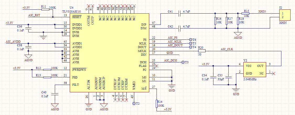
    The pin FC,M0,M1 are connected to GND.The pin M/S is connected to +3.3V.So I don't configure the secondary communication.

    The pin MCLK is connected to 2.048MHz crystal.I used the oscilloscope to test the pin FS,and measured the falling edge of two successive  frame-sync signals.FS = 8000Hz.So I think the sample frequency is 8000Hz.But I think the Control Register 2 is 0x04 because of the entire register configuration array.So I don't know what is the matter,and Where is my configuration wrong.

    Thank you.

    Best regards,

    Wengang Zhao.

  • Hi, Wengang,

    Thank you for the information that you provided.

    It seems that the secondary communication request can be made by placing the device in the 15-bit DAC mode and making the LSB of DIN high. Could you try configuring register 1 as 0x05 please? This is to ensure that the DAC data format will be 16-bit. Could you tell me if there are some changes in the frequency?

    Please let me know if the problem persists.

    Best regards,
    Luis Fernando Rodríguez S.
  • Hi,

    The problem persists.

    Now the entire register configuration array is const Uint16 WriteMCR[] = {
     0xFFFF, 0xFFFF, 0xFFFF,
     0xFFFF, 0xFFFF, 0x0205,
     0xFFFF, 0x0404, 0xFFFF,
     0x0615, 0xFFFF, 0x08C0,
     0xFFFF, 0xFFFF, 0xFFFF,
     0xFFFF};

    There is no change in the frequency.FS is 8000Hz

    But if I configure register 2 as 0x01,I test FS is 32KHz.And if I configure register 2 as 0x02,FS is 16KHz.So I think there still have some configuration problems

    Could you give me an email.I will send some test pictures and schematics to you.

    Thank you.

    Best regards,

    Wengang Zhao.

  • Hi Luis Fernando Rodríguez S;  

        This customer tested the waveform with the FS pin( pin22),and attached is the circuit, I also wonder why the result tested is different with the equation, and we could find that he didn't configure the second communication from the circut and the software configuration.


    Best regards

    Kailyn

  • Hi, Kailyn,

    I already checked the schematic and it seems to be in order. I'm still thinking that it could be related with the secondary communication. This seems to be the only way to produce a different sample frequency on pin Fs. I was reading the register programming section and it seems that the register programming occurs during secondary communication. The NOOP command addresses the pseudo-register and no register programming take place with this command. Could you try the NOOP command please?

    Thank you.

    Best regards,
    Luis Fernando Rodríguez S.