Because of the holidays, TI E2E™ design support forum responses will be delayed from Dec. 25 through Jan. 2. Thank you for your patience.

This thread has been locked.

If you have a related question, please click the "Ask a related question" button in the top right corner. The newly created question will be automatically linked to this question.

TLV320ADC3001 MCLK and BCLK question

Other Parts Discussed in Thread: TLV320ADC3001

Dear Expert,

My customer is drawing schematice with TLV320ADC3001.

BCLK from external device is 48kHz or 44.1kHz, but there's no MCLK.

Is it possible TLV320ADC3001 to work with the 48kHz BCLK?

Here's question for proper schematic.

1. How to terminate MCLK pin of TLV320ADC3001?

2. I want fS to be 48kHz as same as BCLK from external device. Can I set all other parameters to one as below?

PLLCLK_IN=BCLK=48kHz, K=R=NADC=MADC=AOSR=P=1

fS = (PLLCLK_IN × K × R) / (NADC × MADC × AOSR × P)

Thank you in advance.

  • Hi, Kenneth,

    BCLK and WCLK are strongly related. Actually BCLK can be calculated by WCLK. The minimal value for BCLK must be BCLK = WCLK * (number of channels) * (word_length). WCLK is actually the sampling frequency of the device.

    So, if WCLK is 48KHz, there are 2 channels and the word_length is 16-bits, BCLK minimal value must be BCLK = 48kHz * (2) * (16-bits) = 1.536 MHz.

    This device doesn't need a MCLK if the BCLK is used as input. The input clock can be configured by page 0 / register 4. Then, the PLL and the frequency dividers can be used to reach the correct sampling frequency.

    I hope this helps you. Please let me know if you have more questions or comments.

    Best regards,
    Luis Fernando Rodríguez S.

  • Hello Luis,

    Thank you for your kind answer.

    I found there's available MCLK output from SA9302(USB-I2S bridge), and  it has below options.

    44.1K  -> 11.2896MHz (256fs)

    48K -> 12.288MHz (256fs)

    88.2K -> 22.5792MHz (256fs)

    96K -> 24.576MHz (256fs)

    176.4K -> 45.1584MHz (256fs)

    192K -> 49.152MHz (256fs)

    352.8K -> 45.1584MHz (128fs)

    384K -> 49.152MHz (128fs)

    Customer will use 48kHz Fs, and MCLK is 12.288MHz accordingly.

    I suggested below parameter setting for it. Could you confirm please?

    PLLCLK_IN=MCLK,

    P=1

    R=1

    K=8.0 (J=8, D=0)

    NADC=8

    MADC=2

    AOSR=128

    Customer(LG) is requesting simple sample code for below condition.

    1. Init

    2. Recording start

    3. Recording Stop

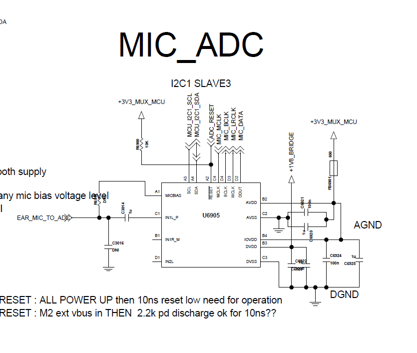
    They're using external Mic bias, IN1L_P only for single ended. Please refer to attached schematic.


    Please review schematic, too.

    Thank  you.

  • Hi, Kenneth,

    I apologize for the late response.

    The PLL configuration seems to be in order. Actually, I suggest not to use the PLL in this case. The MCLK is a multiple of the sample frequency. So, if AOSR = 128, NADC = 1 and MADC = 2, the sample frequency will be 48 kHz (fs = 12.288MHz / (2*1*128) = 48kHz).

    I suggest to take a look of the following script. It is an example script adapted for customer needs:

    Init_record_ADC3001.txt
    # Key: w 30 XX YY ==> write to I2C address 0x30, to register 0xXX, data 0xYY
    # # ==> comment delimiter
    #
    # The following list gives an example sequence of items that must be executed in the time
    # between powering the device up and reading data from the device. Note that there are
    # other valid sequences depending on which features are used.
    #
    # ADC3101EVM Key Jumper Settings and Audio Connections:
    # 1. Remove Jumpers W12 and W13
    # 2. Insert Jumpers W4 and W5
    # 3. Insert a 3.5mm stereo audio plug into J9 for
    # single-ended input IN1L(P) - left channel and
    # single-ended input IN1R(M) - right channel
    ################################################################
    # 1. Define starting point:
    # (a) Power up appicable external hardware power supplies
    # (b) Set register page to 0
    #
    w 30 00 00
    # (c) Initiate SW Reset
    #
    w 30 01 01
    #
    # 2. Program Clock Settings
    # (a) Program PLL clock dividers P,J,D,R (if PLL is necessary)
    #
    # In EVM, the ADC3001 receives: MCLK = 12.288 MHz,
    # BCLK = 3.072 MHz, WCLK = 48 kHz
    #
    # Since the sample rate is a multiple of the input MCLK then
    # no PLL is needed thereby saving power. Use Default (Reset) Settings:
    # ADC_CLKIN = MCLK, P=1, R=1, J=4, D=0000
    w 30 04 00
    w 30 05 11
    w 30 06 04
    w 30 07 00
    w 30 08 00
    #
    # (b) Power up PLL (if PLL is necessary) - Not Used in this Example
    w 30 05 11
    # (c) Program and power up NADC
    #
    # NADC = 1, divider powered on
    w 30 12 81
    
    # (d) Program and power up MADC
    #
    # MADC = 2, divider powered on
    w 30 13 82
    #
    # (e) Program OSR value
    #
    # AOSR = 128 (default)
    w 30 14 80
    #
    # (f) Program I2S word length as required (16, 20, 24, 32 bits)
    #
    # mode is i2s, wordlength is 16, slave mode (default)
    w 30 1B 00
    #
    # (g) Program the processing block to be used
    #
    # PRB_P1
    w 30 3d 01
    #
    # 3. Program Analog Blocks
    # (a) Set register Page to 1
    #
    w 30 00 01
    #
    # (b) Program MICBIAS if appicable
    # MICBIAS to AVDD
    #
    w 30 33 18
    #
    # (c) Program MicPGA
    #
    # Left Analog PGA Seeting = 0dB
    w 30 3b 00
    #
    # (d) Routing of inputs/common mode to ADC input
    # (e) Unmute analog PGAs and set analog gain
    #
    # Left ADC Input selection for Left PGA = IN1L(P) as Single-Ended
    w 30 34 fc
    #
    # 4. Program ADC
    #
    # (a) Set register Page to 0
    #
    w 30 00 00
    #
    # (b) Power up ADC channel
    #
    # Power-up Left ADC and Right ADC
    w 30 51 82
    #
    # (c) Unmute digital volume control and set gain = 0 dB
    #
    # UNMUTE
    w 30 52 00
    

    It explains the initialization code and the record mode. In order to disable the record mode, it would be necessary to mute the ADC (page 0 / register 82) and then turn off the ADC (page 0 / register 81).

    I already reviewed customer's schematic and it seems to be in order. I didn't find anything to change. Just remember to follow the Layout recommendations.

    Best regards,
    Luis Fernando Rodríguez S. 

  • Hello Luis,

    Thank you very much.

    It's quiet on time and we could deliver right support by your help.

    We advised not to use PLL.

    I think the init code you've sent is pretty useful for the SW bring up.

    I'll let you know uf if therer's further support needed.