This thread has been locked.

If you have a related question, please click the "Ask a related question" button in the top right corner. The newly created question will be automatically linked to this question.

Weird behaviour when using LM380 as dual supply

Other Parts Discussed in Thread: LM380, LM384

hello

In an applications note about the LM380 , it shows that it can be used to make a simple dual power supply:

www.ti.com/.../lm380.pdf

I applied the configuration mentioned in the application note, and it seemed an outstanding solution for my problem (I needed a compact dual supply for an experiment for my students) and for what I need. but I was very disappointed after I implemented the circuit, because I found that the LM380 goes very hot even if there is no load at all!

why it goes that hot even there is no load?

  • Hi Mostafa,

    I would like to ask you some questions:
    Could you share your schematic?
    What do you mean with a dual power supply? Are you trying to use the LM380 with possitive/negative supplies?
    What app note are you referring?

    I also want to remind you that LM380 is in lifebuy state, you could take a look at other similar devices like LM384 that are still active.

    Best regards,
    -Ivan Salazar
    Texas Instruments
  • hello

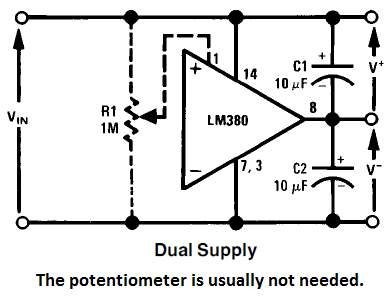
    the following is the schematic that I mean. 

    I got it from ti application note AN-69 figure 19 www.ti.com/.../snaa086.pdf

    the dual supply that I mean, is that to use LM380 to split single supply Vcc into a dual supply Vcc/2 and -Vcc/2

    I heard that it is in lifebuy phase, but still we have it in stock and I want to know how to apply the schematic that you mentioned in application note so I can make benefit of LM380 that I have.

    thanks

  • Hi Mostafa,

    Have you measured the voltage or current at the output?
    Is R1 (the potentiometer) installed in your circuit? have you tried to change the resistance of R1 to see if the heating is diminished?
    The unbalance current could cause the heating.
    Is there any difference between loading and not loading the output?

    Best regards,
    -Ivan Salazar
    Texas Instruments
  • The question has not been asked; what is the input voltage? It states in the data sheet the input needs to be between 10-22VDC. 

    If the input is an AC voltage, it will not work.

    The schematic in question takes advantage of the fact that the device output is VCC/2. Not " Vcc/2 and -Vcc/2". This is an "artificial ground" (which is why "ground" shouldn't be used, "reference" is a better term, but I digress). As such, you really have to keep track of "ground" in your circuit. The input "ground" is NOT the "output ground". Output "ground" is the center point of the two caps... 

    The data sheet also goes into more detail about the type of heatsink needed for this device. I'd be very leary of running this circuit without a heatsink, unless pulling milliamps from the circuit.

    According to the circuit in the DS (figure 5) pin 1 is the internal voltage divider used to bias the input (pin 6). Usually a cap goes from this pin to ground. Forcing a voltage into this pin causes the input structure to be biased differently. 

    What do you have on the inputs, if anything? These are internally pulled to ground via 150K resistors. Doing anything else with them is going to upset the balance on the output.

    Good luck.

    Mike T.

    P.S. It just occurred to me as well; what kind of power supply decoupling do you have? The schematic shown has caps on the outputs referenced to the "rails", but nothing shown on the supply pin (to "ground"). The output *could* be oscillating like hell...