This thread has been locked.

If you have a related question, please click the "Ask a related question" button in the top right corner. The newly created question will be automatically linked to this question.

Unwanted Delay in Start-Up with LM4952 Amplifier

hi everyone
I have a problem with my audio power amplifier circuit :

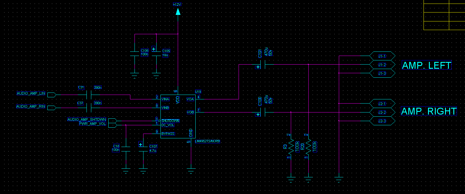
When i power this circuit for the first time (system being off for a long time) everything is O.K. but if i reset input power , amplifier starts again after a long delay (about 2 minutes) and then there is loud "pop & click" at outputs.

Load speakers are 3W and 4 ohm.

Speaker P/N is : AS07104PO-WR-R from PUI Audio Inc.

*Speakers are always connected .
*Inputs to this amplifier is coming from an analog switch which change audio path to this amplifier or external amplifier .
*During this transition speakers are completely silent and there is no noise at all.

Can you help me to fix this problem ?

  • Hi Molla,

    If 470uF and 4.7kOhm have solved your problem it should be fine to use these values.
    You can lower down your values to get a lower RC time constant.
    Besides, the cutoff frequency with these values is almost 0Hz, if you lower down the R and C values you can increase the cutoff frequency closer to 20Hz.
    However, you can keep your current R and C values if it works fine for your application.

    Best regards,
    -Ivan Salazar
    Texas Instruments
  • This is PCB Layout for Top and Bottom :

  • I am not getting any support here.

    I supposed to use this circuit in a mass product system but no expert help me to walk through this problem .

    Please give me a solution.

  • Hi Molla,

    I apologize for the delayed response.
    Your layout seems to be pretty much in line with the recommended design from the datasheet.
    The turn-on time is effectively related to bypass capacitor and the pop and click reduction, although you're using the recommended value for this capacitor.
    Have you tried a turn-on/turn-off procedure?
    For turn-on: Power-on the supply while the device is in shutdown, when the supply is stable then take the device out of shutdown.
    For turn-down: Shutdown the device and then power-off the supply.

    Best regards,
    -Ivan Salazar
    Texas Instruments
  • Thank you for response.

    In datasheet did not mentioned how bypass capacitor related to start-up delay . For example with 4.7uF how much time expected to be delayed in start up ?

    You mean there is a turn on procedure ? If so , I guess I must pull-down shutdown pin with a resistor until micro-controller get handle of shutdown pin because shutdown being control by a CMOS (3.3V logic I/O) micro-controller .

    I try it and post results.

    Thanks again.
  • I think I've found the problem source :

    I've traced BYPASS pin and saw that when I put probe on it, the voltage goes down to almost 1.5V . This maybe is not a problem but
    I had noticed resetting power when BYPASS voltage is zero cause no problem as said in data sheet all capacitors must be discharged during
    power up . So how can I make sure this capacitor is fully discharge during power-up ? Is there any recommended circuit ?
  • Hi Molla,

    Sorry for the late response.
    You could try to add a resistor to discharge the Bypass capacitor while the device is in shutdown. It is not recommended to keep the resistor connected to the Bypass pin when the device is operating as this could affect the Bias reference voltage.

    Best regards,
    -Ivan Salazar
    Texas Instruments
  • You mean for example a MOSFET parallel to BYPASS CAP to discharge it to GND ?
    Some experts giving me an idea included a diode connected to +12v at cathode and BYPASS at anode .
    Any suggestion ? I need a practical solution.

    Thanks for your support.
  • Molla,

    I mean a resistor in parallel with Bypass cap to discharge it, it could be connected through a transistor to avoid the connection of the resistor when the device is operating.
    The diode could also be a solution, I think this solution discharges the capacitor through the power supply circuitry when it is powered down using this circuitry as some kind of equivalent resistance to discharge the capacitor. Although by doing this the capacitor will be acting as power supply when it is discharging but if this is not a concern I think this could be a solution to discharge the capacitor.

    Best regards,
    -Ivan Salazar
    Texas Instruments