This thread has been locked.

If you have a related question, please click the "Ask a related question" button in the top right corner. The newly created question will be automatically linked to this question.

TAS5754M/56M Ignore PLL Lock Detection in P0-R37

Other Parts Discussed in Thread: TAS5756M, TAS5754M

Hi,

The sound quality is degraded if setting the bit for "Ignore PLL Lock Detection [0]" to "1"(the pll unlocks are ignored) in P0-R37.
So, could you please tell us the difference between the internal processing if ignoring this function or not ?
For instance, does the lock range of the pll change by this setting ?

Best regards,
Kato

  • Hi Kato,

    I will try to find more details on this bit.

    Andy
  • Hi Andy-san,

    Thank you for your quick response.
    I am looking forward to getting the information from you.

    Best regards,
    Kato

  • Hi Kato,

    That bit will not affect the PLL lock detection at all. When the bit is set to '1', simply a clock error due to the PLL unlock will not be triggered.

    What do you mean exactly by "the sound quality is degraded"? From my point of view, that bit should not degrade the sound quality if it is set to '1'.

    Andy
  • Hi Andy-san,

    Thank you for your information.
    It is difficult for me to explain exactly since it is an auditory impressions.
    So, I will discuss it with our customer and get back to you.

    Best regards,
    Kato

  • Hi Andy-san,

    Today, I discussed it with our customer, would let you know the information which I obtained from him.
    Actually as a result of having confirmed the sound quality, I felt that it is a weak bass and there is not presence for voice(there is not sharp) as an auditory impressions if setting "Ignore PLL Lock Detection [0]" to "1"(the pll unlocks are ignored) in P0-R37.
    However, it is not an extremely big difference.
    So, I have an additional question.
    Does the pll lock detector of the internal circuit work evne if setting this register to "1" ?
    Or doesn't it work ?
    I guess that the jitter performance for the internal pll is degraded if setting this register to "1".
    Could you please tell me the internal circuit(the circuit topology) for the pll lock detection ?

    Best regards,
    Kato

  • Hi Kato,

    As I explained before, our understanding so far is that that bit will not change the behavior of internal PLL detection circuit. What it controls is the behavior or action after a PLL unlock occurs.

    Did any PLL unlock occur in this customer?

    Andy
  • Hi Andy-san,

    Thank you for your explanation.

    I think that PLL unlock doesn't occur, however have our customer confirm it just in case by using the following register and will get back to you.

    Best regards,
    Kato

  • Hi Andy-san,

    Unfortunately, the pll unlock didn't occur although our customer confirmed the pll lock flag register.
    So, is there any points to be worried about ?

    Best regards,
    Kato

  • Hi Andy-san,

    Could you please disclose the internal circuit regarding "Ignore PLL Lock Detection [0]" since we would like to discuss with our customer on this issue ?
    We would really appreciate it if you could cooperate.

    Best regards,
    Kato

  • Hi Kato,

    As I mentioned before,  if  the customer can confirm that the PLL unlock event doesn't occur at all by checking the P0-R4 bit,  this bit will NEVER cause a clock error and therefore the customer system should behave the same whether this bit is set to 1 or 0.

    Andy

  • Hi Andy-san,

    Thank you for your comment.

    As you mentioned, I have already told to our customer that TAS5756M should work in the same way if the pll unlock doesn't occur.
    However, he is not still convinced and would like to continue investigating.
    Therefore, he demanded the disclosure of the internal circuit or the internal block diagram.
    We kindly ask for your cooperation since it is hard to convince him.

    Best regards,
    Kato

  • Hi Kato,

    OK. Let me try to offer you more details. It might take some time.

    Andy
  • Hi Andy-san,

    Thank you for your strong support.
    We are looking forward to getting that information from you.

    Best regards,
    Kato

  • Hi Andy-san,

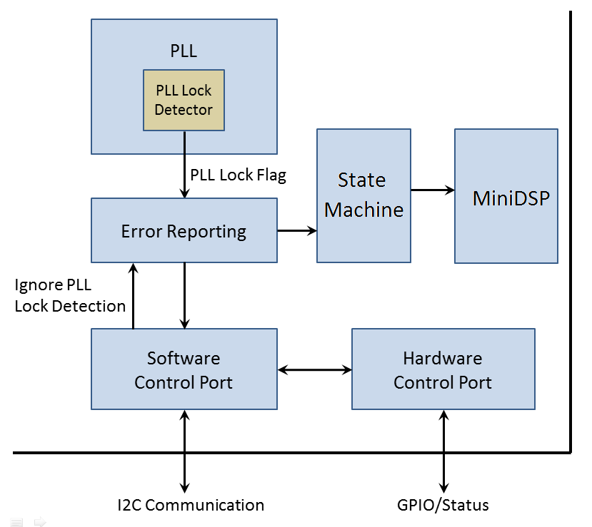
    The internal block diagram which I am considering about "Ignore PLL Lock Detection [0]" is shown as below.
    Could you please confirm it and give me your advice ?

    Best regards,
    Kato

  • Hi Kato,

    Let me try to confirm that for you.

    Andy
  • Hi Andy-san,

    Thank you for your quick response.
    I am looking forward to hearing your comment.

    Best regards,
    Kato

  • Hi Kato,

    Your block diagram is basically OK.  Just some details are misinterpreted. The PLL lock flag is monitored by a state machine inside the device. When a PLL unlock event occurs,  the state machine will notify the miniDSP to go to the power down mode.

     Andy

  • Hi Andy-san,

    Thank you for confirming.
    I understood and will inform our customer of this information.

    Best regards,
    Kato

  • Hi Andy-san,

    As a result I sent the block diagram to our customer, I obtained an additional question from him.
    Could you please give me your advice since he would like to know which of the "Error Reporting" block and the "State Machine" block has the function to ignore the pll unlock if setting "Ignore PLL Lock Detection [0]" to "1" in P0-R37 ?

    Best regards,
    Kato

  • Hi Kato,

    That's is a good question.  I think it might be better to consider the "Error Reporting" and "State Machine" as one block.  Those "Ignore" bits can be regarded as the software switches inside this block.  I will let you know if I can find different explanations.

    Some questions for you.

    a) I think the customer is using a 3-wire I2S, right?

    b) Have they tried to use an AP to duplicate the same issue?  The I2S signals from AP are supposed to be very stable.

    And one suggestion for you. 

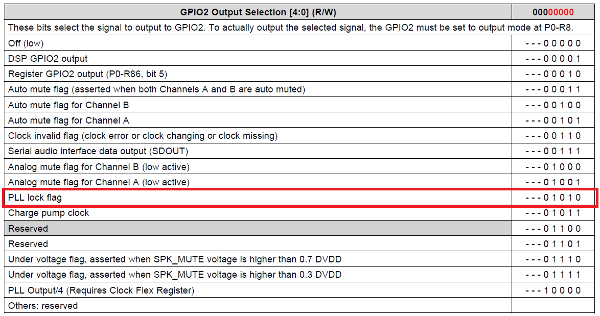
    GPIO0/1/2 can be configured to output the PLL lock flag (See the screenshot below). It is a good approach to determining whether any PLL unlock event occurs when the "Ignore" bit is set to '1' or '0'.  

    Andy

  • Hi Andy-san,

    Thank you for your reply.

    Here are my comments.

    a) Yes.
    b) No, he has used his set only.

    Could you please tell me how to occur the pll unlock event only using an AP easily ?
    I believe that not only the pll unlock event but also the clock error occurs if halting the SCLK.
    Could you please give me your advice ?

    Best regards,
    Kato

  • Hi Kato,

    See my comments below:
    a) Could you please tell me how to occur the pll unlock event only using an AP easily ?
    Andy : What I was trying to say is to use an AP as the i2s input to their system, toggle the "Ignore" bit and see whether any PLL unlock event could happen. I personally don't think they will see the issue if they try this approach.

    b)I believe that not only the pll unlock event but also the clock error occurs if halting the SCLK.
    Andy : Yes, a PLL unlock will cause a internal clock error, which later will put the device into the power-down mode if the "Ignore" bit is set to '0'.

    Andy
  • Hi Andy-san,

    Thank you for your support.

    I evaluated the pll lock flag via GPIO2 pin when halting SCLK.
    As a result, the pll lock flag doesn't depend on the setting for "Ignore PLL Lock Detection" in P0-R37.
    The indicator is "1" when the pll is locked and is "0" when the pll isn't locked.
    So, I believe that "State Machine" block has the function to ignore the pll unlock.

    Furthermore, I have discovered a new issue.
    TAS5754M did not rarely transition to the power-down mode when setting "Ignore PLL Lock Detection [0]" to "1" in P0-R37 and occurring the clock errors only.
    So, the pwm outputs continued to switch at 283kHz as below.
    Could you please immediately investigate it ?

    Best regards,
    Kato

  • Hi Kato,

    No problem. You may have to tell me what your test conditions are and how to replicate that issue step by step. I just did a quick test by myself and didn't see the same issue.

    Andy
  • Hi Andy-san,

    Thank you for your support.

    The replication procedure is shown as below.
    I believe that the "State Machine" block causes this issue since it doesn't occur if setting 0x25 to 58h.
    In addition, it might be related to sound quality degradation.
    Could you please continue to investigate it ?

    <Replication Procedure>
    1. Power-on(PVDD=15V)
    2. Connecting TAS5754M EVM to PC via USB Cable
    3. Starting PPC2 and Selecting TAS5754M-56MDAEVM
    4. Selecting Hybridflow5 and Downloading it
    5. Selecting Advanced Mode
    6. Setting Volume Controls to -10dB for Out A and Out B
    7. Selecting Direct I2C Read/Write Tab and Execute the Following Script

       w 98 00 00
       w 98 02 10
       w 98 25 59
       w 98 0D 10
       w 98 08 20
       w 98 55 0a
       w 98 28 03
       w 98 02 00

    8. Applying MCLK, SCLK, LRCK and SDIN via AP
    9. Removing MCLK
    10. Repeating to Remove SCLK and Apply SCLK

    Best regards,
    Kato

  • Hi Kato,


    I didn't see your reply until just now. I will look into it tomorrow.

    Andy

  • Hi Andy-san,

    No problem.
    I am looking forward to hearing your comments tomorrow.

    Best regards,
    Kato

  • Hi Andy-san,

    Could you please let me know your progress on this issue ?

    Best regards,
    Kato

  • Hi Kato,

    I followed you steps but failed to see the exactly same issue you reported. I tried again this afternoon and the same result.

    Which revision is your PPCMB? I will try again tomorrow.

    Andy
  • Hi Andy-san,

    Thank you for your support.

    I have used the PPCMB revision D, so I tried to evaluate the TAS5754M evm using the PPCMB revision F since I also have it.
    As a result, this issue have been replicated, therefore doesn't depend on the PPCMB revision.
    This issue should exactly occur if setting 0x25 to 59h and halting I2S clocks only as below.

    Best regards,
    Kato

  • Hi Kato,

    OK. Now I know how you stop and start the BCLK again. What I did is to pull out the BCLK and then put it back.

    Let me try again. 

    Andy

  • Hi Andy-san,

    Thank you for your support.
    I am looking forward to getting your information that this issue have been replicated.

    Best regards,
    Kato

  • Hi Kato,

    After you disabled the PSIA output in the AP, you could still see the 283KHz PWM output at the speaker terminals. Is that correct?

    Andy
  • Hi Andy-san,

    Yes, this issue hasn't been closed.

    Best regards,
    Kato