Because of the holidays, TI E2E™ design support forum responses will be delayed from Dec. 25 through Jan. 2. Thank you for your patience.

This thread has been locked.

If you have a related question, please click the "Ask a related question" button in the top right corner. The newly created question will be automatically linked to this question.

TAS5342LA: TAS5342LA BTL configuretion

Guru 16770 points
Part Number: TAS5342LA

Hi

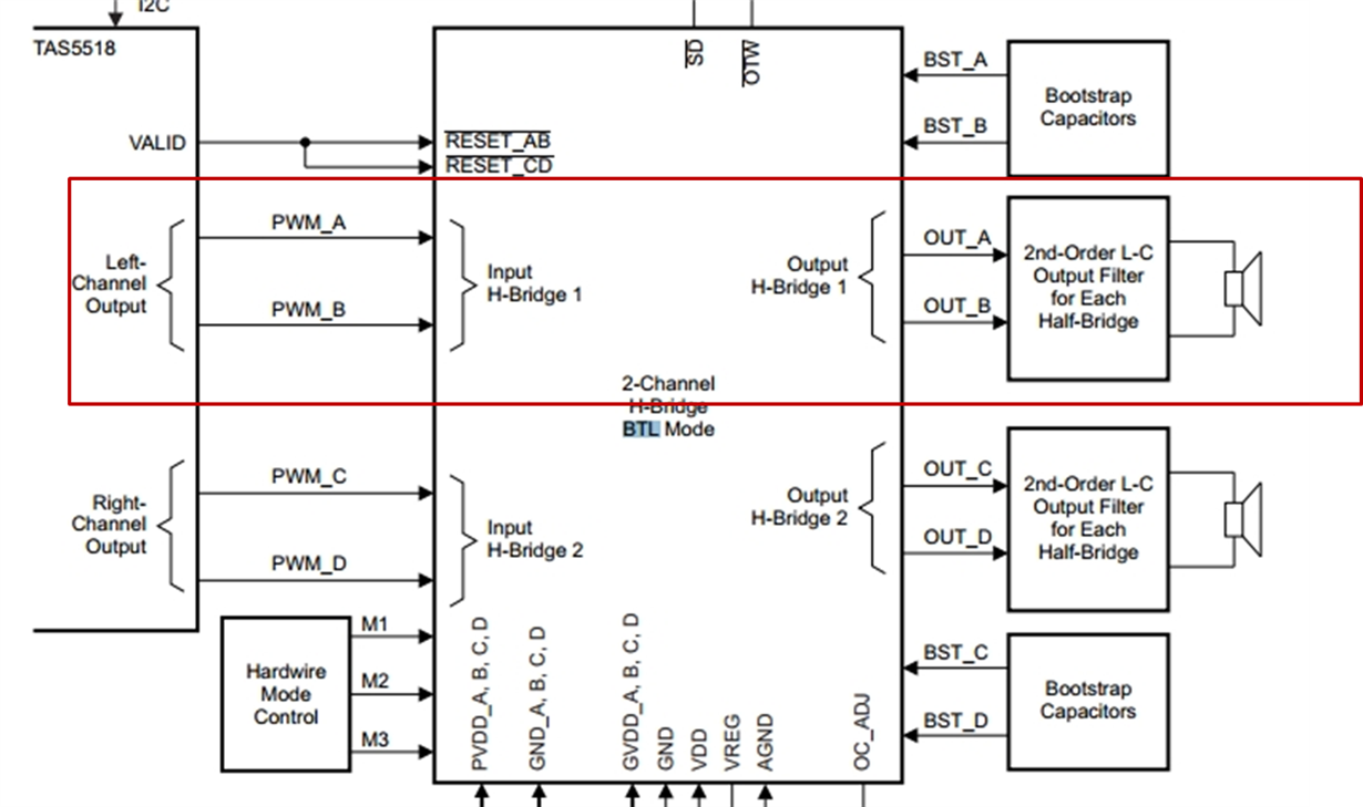
I am reffering typical 2N BTL application configuration but the 1ch output is required.

I suppose BD modulation, so I think it would need differential (2N) configuration.

I think I would need the configuration within a red frame like the following image.
So I want to know how to terminate unused ports.

1.
How to terminate C-side and D-side outputs?
How about PWM_C and PWM_D inputs?

2.
What kind of the setting of mode pin is recommended?
(M3:M2:M1=0:0:0?)

3.
According to the datasheet, BTL configuration is implemented with A+B and C+D.
Is it possible to use A+D? (Considering aspect of temperature)

BestRegards

  • Hello,  It is possible to use A+B and Disable C+D. 

    See page 16 of the Datasheet.  This describes the Device Reset.  As shown in the image you provided, the TAS5342LA has separate Reset pins for AB and CD.  holding pins CD low will keep the output of Out_CD in a Hi-Z state.  You will still need to provide power to the GVDD_C, GVDD_D, PVDD_C, and PVDD_D. Additionally it is best to ground PWM_C and PWM_D. The mode setting will depend on if you are using a  differential PWM (2N) or Single PWM (1N) 

    the 2N mode would be  M1:M2:M3 = 0:0:0   <<<---this is 2N mode with all protection systems enabled. 

    the 1N mode would be   M1:M2:M3 = 0:1:0  <<<--- This is 1N mode with all protection systems enabled. 

    see page 17 of the datasheet for more info on the Mode settings.   

    There is no way to use A+D. 

    The new TPA32xx series have the ability to be set in pre-filter PBTL mode.  This mode would allow you the same component count as BTL, but with much greater efficiency. that would help alleviate the thermal concerns you have also. Unfortunately these are not PWM input devices; however, if your design has some flexibility,  these devices would be a good option.