Hello community,
I have an existing and hardly documented design in front of me that was used for a test circuit. It purpose was to modulate a LF signal onto a 40 kHz base band signal for ultrasonic emitters. Unfortunately we need to build up some more of this test circuits and now I have the challenge to make it work. PCBs are populated and while checking the function of the device I found out that the used TAS5715 IC is making some trouble.
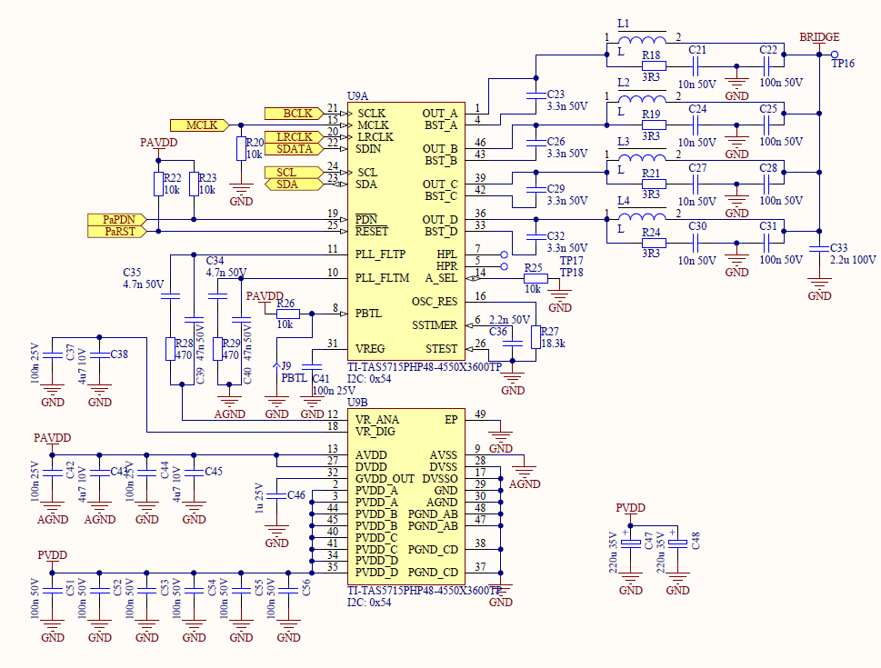
Here a picture of the schematic drawing. The inductors L1-L4 are populated with 15nH.
The signal "Bridge" goes to the 40kHz Amplifier and is connected for testing purpose to a small speaker via a DC decoupling capacitor of 10 nF.
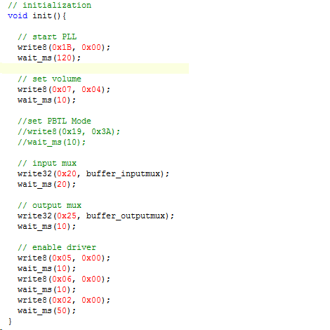
To give you a better picture I have also included the whole setup routing used for the TAS5715.
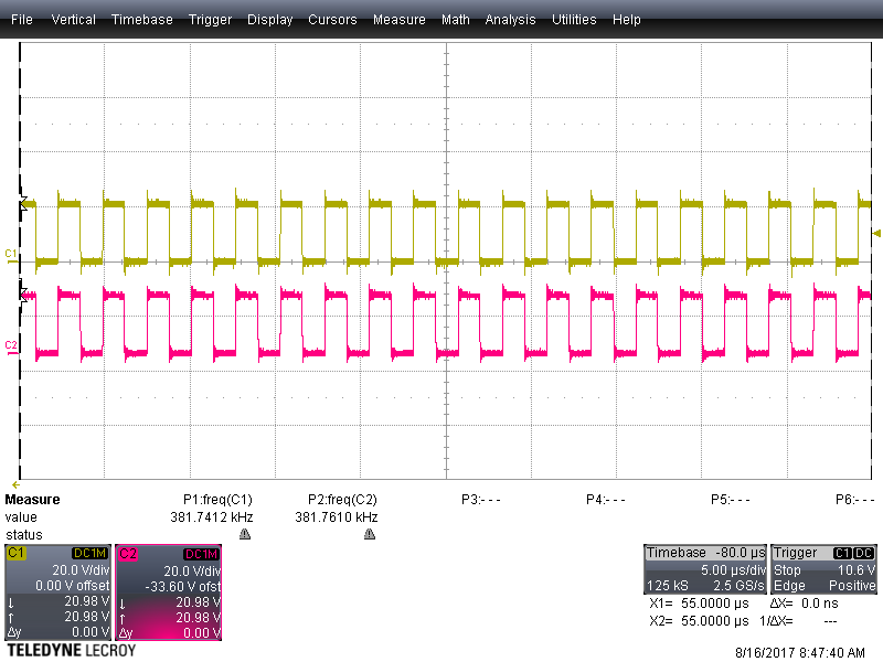
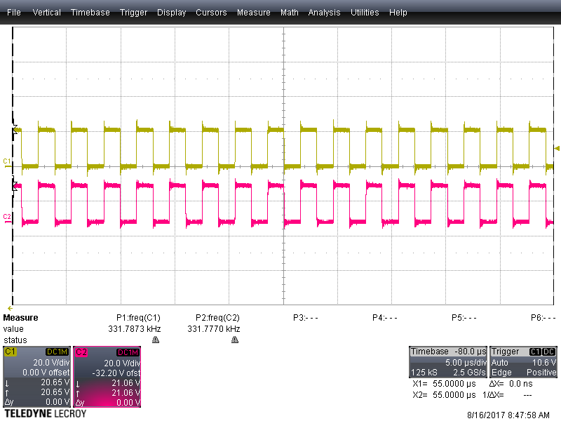
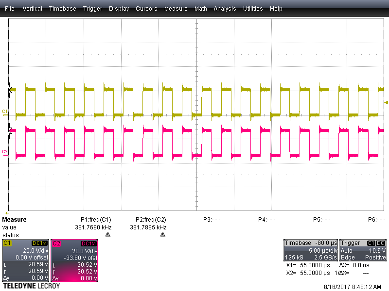
What I have observed so far. The sound of the TAS is chopped. Half a second sound the next half second cracking and creaking noises. Chip and Inductors are getting pretty warm, even in "Idle" mode without any sound signal on the I2S Pins. Current draw is about 330 mA for the TAS. From the datasheet I found a section that states to set register #19 to the value 0x3A while using PBTLE mode. This section is commented out in the setup routine. By enabling this register access the circuit is set to a non working mode where our power supply goes into over current protection. The I2S data is okay. Checked it with an additional amplifier in parallel. No trouble found for the I2S signal (48kHz, 256fs). Voltage supply's are also stable. The only thing that comes to my mind is the strange way used to establish the PBTL connection of the outputs. But I was told that the old circuits are working. So I hope that some of you have an idea to what I'm missing right now.
Best regards,
Christopher


