Because of the Thanksgiving holiday in the U.S., TI E2E™ design support forum responses may be delayed from November 25 through December 2. Thank you for your patience.

This thread has been locked.

If you have a related question, please click the "Ask a related question" button in the top right corner. The newly created question will be automatically linked to this question.

SRC4190: Connect two I2S clock masters

Part Number: SRC4190

Hi all,

In a design I'm working on I need to connect two devices over I2S. Obviously one has data input and the other data output, but, unlike many other devices (especially the receiver), both devices want to be the I2S clock master.
I can not change this. It would be a lot easier if I could, I know, but it can not be done.

So, I have to connect two I2S clock masters to each other.
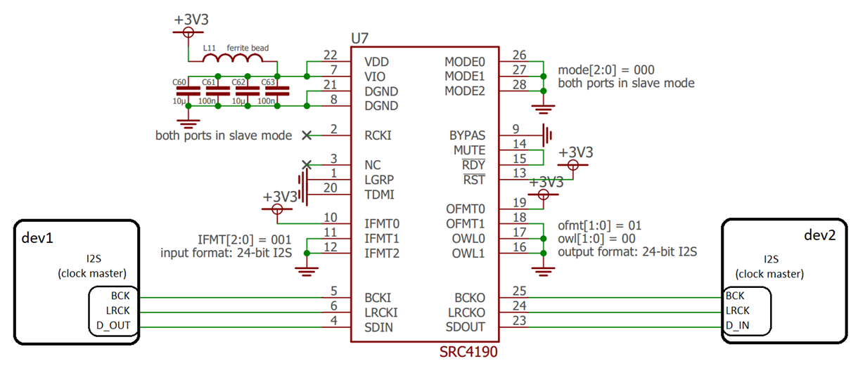
What I've come up with, and I honestly know no other option, is to make use of an asynchronous sample rate converster (ASRC). I choose the SRC4190 from TI in the design and configured it as I2S slave input and I2S slave output so I can hookup two I2S masters.

It's a hardwired configuration, see my setup below:

According to the datasheet, this should work. I see no reason why it would not.
However, we have just build an actual prototype of the whole design and this ASRC seems not to work.

I've measured the SRC I2S input (pin5, 6, 4) and this is fine.
Also, the same I2S signals are going to another device elsewhere in the design and there is no problem, so I'm sure the I2S is appearing valid at the SRC input.

At the SRC I2S output (SDOUT, pin 23) I measure nothing however, it just stays low.

Can anyone please validate the design above?
A TI-engineer already told me this would work fine when I asked this in another (sub)tread on the Audio Amplifier forum. However without showing this schematic.

What else can be causing this? Have I set the configuration wrong?
I really don't understand.

Thanks in advance!
Kind regards!

  • Hi Julien,

    Section 8.2.2.1 in the datasheet says "The SRC4190 requires a reference clock for operation..." Personally I've never set the device up in the way that you are using it so I'm going to order an evaluation board so that I can duplicate your setup. That should be here tomorrow. I will let you know if that solves the problem. In the meantime, if you are able, try connecting one of the MCLKs to RCKI to see if that solves your problem.

    best regards,

    -Steve wilson
  • Hi Steve,

    I totally missed out on that section! That explains a lot! Thank you for pointing out.
    Is there a preference in who should dictate the RCKI clock (MCLK from dev1 vs MCLK from dev2)?

    I'll try it out on Monday since I don't have the prototype on hand right now.
    Thank you for your effort in duplicating the design for validating. Really appreciate it.

    Kind regards,
    Julien
  • Ah yes, it is friday... I wont be able to have the board until monday afternoon. So let me know how your experiment goes. My guess is that this should solve the issue.
    best regards,
    -Steve
  • Julien,

    The EVM didn't arrive today, but I got a notification that it should arrive tomorrow morning. I apologise for the delay. I will test your configuration when It arrives.
    best regards,
    -Steve Wilson
  • Hi Steve,

    Meanwhile I succesfully patched the dev2's MCLK to RCKI, and I can confirm this resolved my issue.

    I took the MCLK of dev2 simply because I had easy acces (there is a clock fanout buffer on this MCLK since it's distributed elsewhere in the design).
    I didn't try the MCLK of dev1 but I suppose it will work as well.

    Thank you for your effort!

    Best regards,
    Julien