This thread has been locked.

If you have a related question, please click the "Ask a related question" button in the top right corner. The newly created question will be automatically linked to this question.

TPA2050D4: Is it compatible with ATMEGA328?

Part Number: TPA2050D4

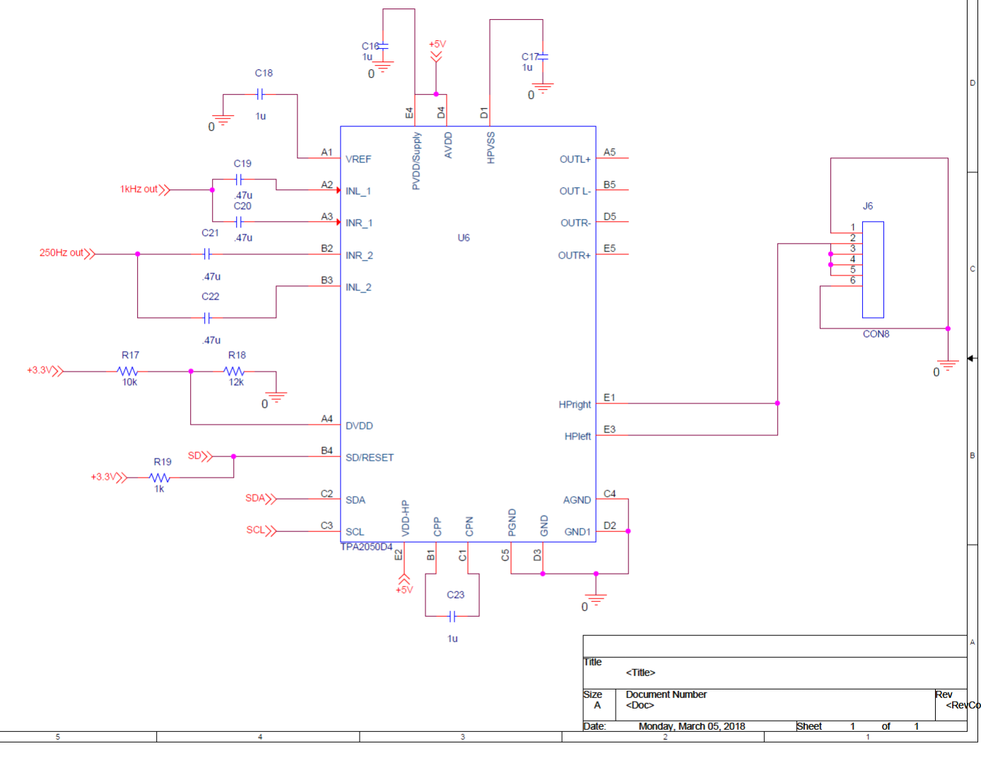
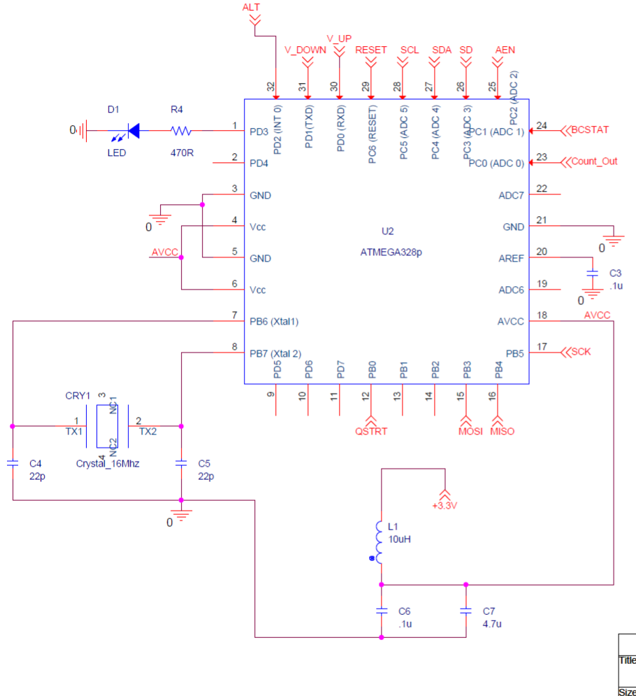
Hi, I am trying to design low cost audio amplifiers for headphones with volume control (I2C) using ATMEGA328. So I want to deactivate class D amplifiers, activate only DirectPath for headphones. For now I am just trying to give a fixed volume. I checked the voltage levels at input, its around 0.25/0.11V and varying. However, I am not getting any output signal from TPA2050D4. Also, I am not sure if I am coding the device TPA2050D4 right. Not sure if its the coding issue, or my schematics, or if TPA2050D4 is compatible with ATMEGA328. Can anyone please help me on where I could be wrong.

ArdinoCode.txt
#include <Wire.h>
#include <avr/sleep.h>
int num=0;

void setup()
{
  
  Wire.begin();
  
  pinMode(A3, OUTPUT);
  digitalWrite(A3, HIGH);

  pinMode(3,OUTPUT); //debug to led 3


//power amp setup
Wire.beginTransmission(0xE0); //write enable register

    if(Wire.available()) {
        num = 1;
       
      }
     
  
  Wire.write(0x02);  // register address 0X02
  if(Wire.available()) {
        num = 1;
       
  }
  Wire.write(0x0C);  // SWS '0', HPL and HPR enabled, class D disable
  if(Wire.available()) {
        num = 1;
   
  }
 Wire.endTransmission();
  delay(100);

Wire.beginTransmission(0xE0); //write enable register
    if(Wire.available()) {
        num = 1;

  }
  
  Wire.write(0x03);  // register address was 0X03
  if(Wire.available()) {
        num = 1;

  }
  Wire.write(0x81);  // LIM_LOCK enable, mode 001, I want this at the heaphones 
  if(Wire.available()) {
        num = 1;

  }
 Wire.endTransmission();
  delay(100);

Wire.beginTransmission(0xE0);
    if(Wire.available()) {
        num = 1;

  }
  
  Wire.write(0x05);  // register address was 0X05
  if(Wire.available()) {
        num = 1;

  }
  Wire.write(0x13);  // volume
        num = 1;

  }
 Wire.endTransmission();
  delay(100);

Wire.beginTransmission(0xE0);
    if(Wire.available()) {
        num = 1;

  }
  
  Wire.write(0x06);  // register address was 0X06
  if(Wire.available()) {
        num = 1;

  }
  Wire.write(0x13);  // volume data
  if(Wire.available()) {
        num = 1;

  }
 Wire.endTransmission();
  delay(100);


  Wire.beginTransmission(0xE0);
    if(Wire.available()) {
        num = 1;

  }
  
  Wire.write(0x07);  // register address was 0X07
  if(Wire.available()) {
        num = 1;
  }
  Wire.write(0x12);  // HP voltage and gain
  if(Wire.available()) { 
        num = 1;

  }
 Wire.endTransmission();

  delay(100);
  
}


void loop()
{

if(num ==1){
digitalWrite(3,HIGH);
}  

}

  • Hi Arvind,

    Welcome to E2E, thanks for your interest in our devices.
    I will be responding tomorrow as I am out of the office.

    Best Regards
    José Luis Figueroa
    Audio Applications Engineer
  • Hi Arvind,

    The schematic seems to be correct.
    I can just help you to review the register map as I am not an expert in Atmel microcontrollers, so Could you provide me the register map?
    I am not sure that you are configuring the device in your Atmel code. You need to configure the register map before using the device.

    Best Regards
    José Luis Figueroa
    Audio Applications Engineer
  • Hi Luis,

    Thanks for your reply.

    I have used following register addressing. I require output only from headphones HPL and HPR. I wont be using speaker. So I am deactivating Class D amplifier

    Begin transmission with "0XE0" (TPA2050D4 write address)
    Write to register: 0X02
    Data to 0x02 : 0x0C (TPA active, head_phones active, power amp inactive)
    End transmission

    Begin transmission with "0XE0" (TPA2050D4 write address)
    Write to register: 0X03
    Data to 0x03 : 0x81
    (LIM_LOCK active, Mode 001. Here please let me know if I can use mode 001 to get output at HPL and HPR, In the circuit, I have also shorted HPL and HPR at the output and then connected it to AUX connector. Is this okay?)
    End transmission

    Begin transmission with "0XE0" (TPA2050D4 write address)
    Write to register: 0X05
    Data to 0x05 : 0x13 (Set volume, this will affect the volume of HP right?)
    End transmission

    Begin transmission with "0XE0" (TPA2050D4 write address)
    Write to register: 0X06
    Data to 0x06 : 0x13 (Set volume)
    End transmission

    Begin transmission with "0XE0" (TPA2050D4 write address)
    Write to register: 0X07
    Data to 0x07 : 0x12 (HP_Vout and HP_Gain)
    End transmission

    Also, could you please tell me the exact powering sequence?
    I am providing 3.3V to DVDD first. And then powering up PVDD and VDDHP. Post which I provide RESET with 3.3V. I understand from your datasheet there will be a turn-on pop however will this damage the device? Or can I let it function this way?

    Also is it okay to provide SDA, SCL and RESET with 3.3V, as long as I keep DVDD at 3.3V?

    Please let me know.

    Thanks!
  • While scanning for devices, the TPA2050D4 showed address as 0X70. However after including the write bit, I need to address it as 0XE0. Right?
  • Hi Arvind,

    I analyzed your register configuration and the device should work fine. You should get an output signal at HPL and HPR with this configuration. Besides, volume control affects the volume of HP. I think the problem is in the Arduino code.
    This power sequence shouldn't damage the device. On power-up, you should ensure that the AVDD and VDDHP voltages have settled and DVDD is at least 1.7V before setting Reset to logic high. You can refer the Start-up Sequencing and Shutdown Control section of the datasheet if you want to avoid pop noise.
    It is always recommended to supply with 1.8V the digital circuits (SDA, SCL, and RESET). But you can also supply them with 3.3V.
    The TPA2050D4 I2C address is 0xE0 for writing and 0xE1 for reading.

    Best Regards
    José Luis Figueroa
    Audio Applications Engineer