This thread has been locked.

If you have a related question, please click the "Ask a related question" button in the top right corner. The newly created question will be automatically linked to this question.

TAS5162: Amp config modes and protection questions

Part Number: TAS5162

We are working on a upper segment class D audio amplifier and selected TAS5162 as the output stage. After studying the datasheet we have a few questions 

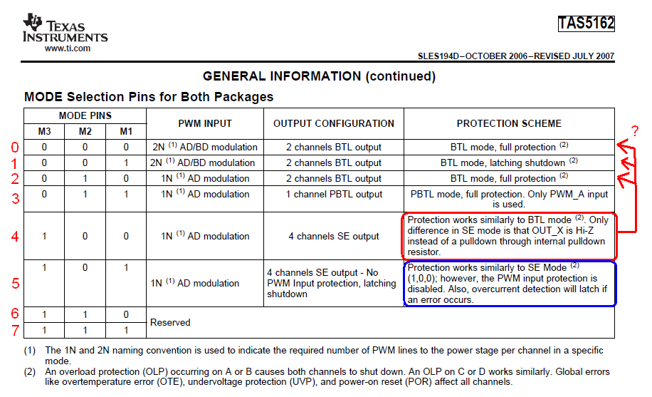
Question 1. Box marked in red on the attached picture. Mode 4 says:

Protection works similarly to BTL mode.

But which BTL mode? Because there are 3 BTL modes, and they have different protections.

Mode 0 and 2 have full protection, and mode 1 has latching protection. Do mode 4 have full protection as modes 2/0, or have latching protection as mode 1?

Question 2:  Box marked in blue on the attached picture.

the PWM input protection is disabled.

Does it mean that PWM duty cycle is not monitored and there are no automatic protection mechanisms ? So is it possible to use for example 99% duty cycle instead of 97.1% (of course in situation where High Side powering are provided in other way than bootstraping, for example using isolated DC/DC converters)?  

Question 3. What does full protection and latching protection mean ? Is it, to understand it in more precisely, probing protection and latching protection? By probing we mean auto restarting from overcurrent, for example in periods of 1 second. And do we understand correctly that latching is permanent, so manual reset is  required ?

Question 4. Are we right that the only difference between mode 0 and mode 4 is that in the SE mode OUT_X is Hi-Z instead of a pulldown  through internal pulldown resistor ?

And we are aware that Mode 0, although it is a BTL stereo mode, has independent 4 PWM inputs. So it may be possible to drive PWMs independently, creating 4 SE outputs. We don't see any information that Mode 0 or 1 checks if PWM inputs is in antiphase (A = B+180, and C = D+180) ?

Question 5. Is the protection reaction automatically executed on all pairs A/B and C/D in all modes? For example in mode 4 (4 independent SE outputs) if overcurrent occurs in output A, does output B also shut down?

Question 6. There is one SD output, are we right then that it is not possible to check what PWM signal pair has shut down ? And  is it necessary to reset all outputs (using RESET_AB and RESERT_CD) in all overcurrent situations ?


Regards, Pawel


  • Pawel,

    1) The difference between "full protection" and "latching shutdown" is minor, both protect the device. In Full Protection the device will use the current limiting feature to attempt to reduce the output current in an OC event. If it cannot be reduced, the amp shuts down. In Latching mode, the amp is simply shut down in the case of an OC event. Mode 4 has full protection with the caveats mentioned in the red box.

    2) The stuck high or low protection is disabled. Let me check on the duty cycle requirement.

    3) See answer (1). Also, Full protection occurs very fast, much quicker than 1 second. It's meant to allow for very brief spikes of overcurrent in case of a music transient, bass hit, sharp sound, etc. The auto-reset from fault requires the system microcontroller to sense the OTW or SD pins and then toggle RESET.

    4) We recommend only using BTL mode for BTL output and SE mode for SE output. We cannot support/guarantee/advise on using SE output with the device in BTL mode.

    5) No, they are independent.

    6) You are correct, the SD pin is global, there is no indication of which half bridfe(s) are shut down. You should be able to Reset only the affected outputs.

    Regards,

    -Adam
  • Thank you for your quick answers.

    But i ask more precisely:

    1) The difference between "full protection" and "latching shutdown" is minor, both protect the device. In Full Protection the device will use the current limiting feature to attempt to reduce the output current in an OC event. If it cannot be reduced, the amp shuts down. In Latching mode, the amp is simply shut down in the case of an OC event. Mode 4 has full protection with the caveats mentioned in the red box.

    In Full Protection, SD indicates any OC event (when protection circuitry trying to limit current), or only when protection circuitry shuts down the half-bridges?

    4) We recommend only using BTL mode for BTL output and SE mode for SE output. We cannot support/guarantee/advise on using SE output with the device in BTL mode.

    Must be a difference in behaviour of TAS5162 in this two modes, since You reccomend to use only BLT mode for BLT output.  Could You explain what functionality in TAS circuitry is changed when mode ich changed between mode 0 and mode 4?

  • Pawel,

    The protection that tries to reduce the output current in an OC event is not reported on the SD pin, only when the system Shuts Down is the SD pin triggered.

    There are many differences, the most common being that the device protection expects the outputs to match the mode that the device is set to. Not following the datasheet here can result in damage to the chip/system/protection features.

    Regards,

    -Adam
  • Pawel,

    Coming back to your question about the PWM input protection. We only check here if the PWM input is within the accepted duty cycle range. If the duty cycle is too low or high, the amp stops switching.

    What is your application and goal with this design? If you can explain the reasons for your configuration and questions, we can help you solve them easier.

    Regards,

    -Adam
  • The protection that tries to reduce the output current in an OC event is not reported on the SD pin, only when the system Shuts Down is the SD pin triggered.


    Thanks.


    There are many differences, the most common being that the device protection expects the outputs to match the mode that the device is set to. Not following the datasheet here can result in damage to the chip/system/protection features.

    Yes, but this not explain what is the difference in circuitry. So our questin is, what changes in circuitry inside TAS5162, that enabling protection circuitry to protect outputs better when mode is equal to real used mode (for example, when selected mode is BTL and speakers is connected as BTL). And protect worst when selected mode is not eual to real mode (when selected mode is SE and speakers is connected as BTL, or vice versa).

    Out intention is to understand really good what protection circuitry works in all modes. Because we want to design uncommon amplifier, when in BLT mode PWM inputs may not be in antiphase (we mean method similar to fast-decay and slow-decacy, method used in driving electrical motor using PWM and half-bridges).

    So we need to know, if there are any issues when we use BTL mode with non-symmetric PWM input signal pairs.
    Or when we use SE mode to create BTL outputs.

  • Pawel,

    I cannot explain this, the information is classified and the chip was designed to work correctly for the connected mode given the best protection we can offer.

    If you can explain your goals and needs, we can help you decide which mode and configuration to use.

    Regards,

    -Adam
  • Generally we want to use something like BTL mode, but there ale some frills.

    A) PWM on A and B inputs (also on C and D) may not be symmetrical.

    It may be non-symetrical (not in phase), as in this picture:

    So there will be the moments when both A and B outputs will be in low or high state at the same time.

    B) For other reasons (used complex LC filter) the instantaneous current sinks from A output may not be equal to current sourced by B output.

    So we thought that using SE mode will be better, because this mode may be better optimized to non-correlated PWM signals and non-correlatet currents (because SE mode not expects same signals in A and B terminals, this mode thinks that A and B are separated cannels).

    But SE mode have specified much worse THD performance. So if it possible to set BTL mode in our application, and it not colliding with frills mentioned above, we preffer to set BTL mode against set SE mode.

  • Pawel,

    The scheme shown above should work with the standard BTL mode and configuration, it's similar to BD mode which we already support.

    Regards,

    -Adam
  • Yes, it will be something like BD mode (but not exactly BD mode).

    We have another question about PBTL configuration (PBTL mode, and PBTL connected load).

    In this situation each H-bridge sees halt of load (means, double od impedance of load). In BTL H-bridges see all load (1 x impedance).

    So equal loading od H-bridges occurs when PBTL is loadet witch 2 times smaller impedance of speakes, in comparsion to BTL.

    For example, 8R for BTL equals 4R for PBTL.

    We expected similar THD performance of this two connections.

    But THD graphs from datasheets show something different. We edited figures to facilitate reading:


    Where can the differences come from?

  • Pawel,

    The load is not exactly shared between the two pairs of outputs when in PBTL mode. The RDSON of the output FETS is effectively half and double the current is available but things like output filter and device internals effect the THD performance as well.

    Regards,

    -Adam
  • Thank You again for Your help.

    But the THD in PBTL mode is lower than THD in BTL mode. So (eventually) non-equal current sharing not destroy THD performance. But something different phenomenon improving THD in PBTL mode.

    Maybe there are an additinal circuitry activated in PBTL mode, that lowering the THD?

    And there is one unansvered question above:

    Adam Sidelsky said:
    2) The stuck high or low protection is disabled. Let me check on the duty cycle requirement.

  • Pawel,

    Some internal nodes can be shared in PBTL mode which gives slightly better performance, that's all I can share.

    The additional answer was already posted:

    "Coming back to your question about the PWM input protection. We only check here if the PWM input is within the accepted duty cycle range. If the duty cycle is too low or high, the amp stops switching."