This thread has been locked.

If you have a related question, please click the "Ask a related question" button in the top right corner. The newly created question will be automatically linked to this question.

TLV320AIC3212: TLV320AIC3212 Digital Microphone

Part Number: TLV320AIC3212

I am currently using the TLV320AIC3212 using Digital Microphone Input (GPI2 is Data, GPIO2 is CLK)

Here is Register Setting, why is there no sound, how can I set it?

###########################################
# Microphone Record through IN1L & IN1R
# need to Insert jumper W15 and W16 for Mic-bias
# AVdd = 1.8V, DVdd = 1.8V, MCLK = 12.288MHz
# PLL Disabled, AOSR = 128, PRB_R1
# Primary I2S interface used with WCLK & BCLK as inputs to the device
##############################################


###########################################
# Software Reset
###########################################
#
w 30 00 00
w 30 7F 00
w 30 01 01
#
###########################################

#########################################################################################
# Clock configuration
# MCLK = 4.096 MHz, BCLK = 512 kHz, WCLK = 8 kHz (slave)
#########################################################################################
w 30 00 00 # Select Page 0
w 30 04 33 # Set ADC_CLKIN = PLL_CLK and DAC_CLKIN = PLL_CLK
w 30 05 00 # Set PLL_CLKIN = MCLK1
w 30 06 91 # PLL settings: P=1, R=1
w 30 07 18 # PLL settings: P=1, R=1, J=24
w 30 08 00 # D=0000 (MSB)
w 30 09 00 # D=0000 (LSB)
w 30 0b 82 # NDAC = 2, divider powered off
w 30 0c 88 # DAC Power MDAC = 8
w 30 0d 03 # DOSR = 768 (MSB)
w 30 0e 00 # DOSR = 768 (LSB)
w 30 12 02 # NADC Powerdown NADC=2
w 30 13 b0 # NADC Powerup, MADC=48
w 30 14 80 # AOSR = 128
#
###########################################


#############################################
# Initialize the Codec
#############################################
#
# select page 1
w 30 00 01
#
# Disable the weak connection beween AVDD and DVDD
w 30 01 00
#
# set the REF charging time to 40 ms
w 30 7A 01
#
# Set the quick charge of input coupling cap for analog inputs
w 30 79 33
#
################################################


##############################################
# ASI#1 configuration
##############################################
#
# select page 4
w 30 00 04
#
# set ASI#1 16 bits, I2S mode
w 30 01 00
w 30 0A 00

w 30 00 04
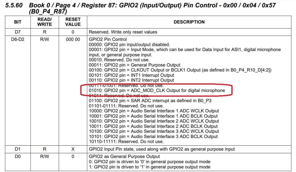
#Digital Mic Data on GPI2 for ASI1
w 30 5C 10

#ASI1 ADC BCLK Output on GPIO2 for ASI1
w 30 57 28
#w 30 16 02

#Digital Microphone Input Pin Control
w 30 65 01
#
################################################

###########################################
# Signal processing
###########################################
#
# Select Page 0
w 30 00 00
#
# Set the ADC PRB Mode to PRB_R1
w 30 3D 01
#
###########################################

#############################################
# ADC configuration
#############################################
#
# Select Page 1
w 30 00 01
#
# Mic Bias enabled, Source = Avdd, 1.62V
w 30 33 40
#
# Route IN1L and CM1 to LEFT ADCPGA with 20K input impedance
w 30 34 80
w 30 36 80
#
# Route IN1R and CM1 to RIGHT ADCPGA with 20K input impedance
w 30 37 80
w 30 39 80
#
# Left Channel Analog ADC PGA = 30 dB
w 30 3B 3C
#
# Right Channel Analog ADC PGA = 30 dB
w 30 3C 3C
#
# ADC Analog programmed for PTM_R4
w 30 3D 00
#
#
# select page 0
w 30 00 00
#
# Power-up ADC Channel
w 30 51 14
#
# Unmute ADC channel and Fine Gain = 0dB
w 30 52 00
#
##################################################
  • Hi, Allan,

    I took a quick  look at the code and noticed that the digital mics are properly configured for each ADC channel , however, the ADCs are turned off (w 30 51 14). The ADCs must be powered for digital mic operation as the internal ADC filters are used by the digital mic interface. Please change settings for register 81  to 0xD4.

    # Power-up ADC Channel
    w 30 51 d4

    Best Regards,

      -Diego Meléndez López
       Audio Applications Engineer

  • This parameter I used yesterday, no use

    The microphone will become the loudest, but there is no sound at all.

  • Allan,

    Can you please clarify your question?. Is the change I proposed effective but now you are getting incorrect data?.

    The problem could be also related to the clock configurations of the codec. Can you please check that the clocks provided to the device matches the clock configurations on the codec?.

    Best Regards,

      -Diego Meléndez López
       Audio Applications Engineer

  • When I type
    # Power-up ADC Channel
    w 30 51 d4
    The microphone volume on the computer will become the maximum

    Normal should be gray, there will be green display beating volume when there is sound

    Do not understand what part of the clock you said, set the code above me not?

  • Is there any advice?
  • Allan,

    As you are using the EVM for this test, you need to make sure the clocks provided by the EVM USB-Audio interface, the TAS1020B, are matching the configurations made on the codec. Have you programmed the EVM to support 8KHz operation?.

    Best Regards,

      -Diego Meléndez López
       Audio Applications Engineer

  • My software settings are all PO, I don't understand how you talk to me about setting problems.
  • My software settings are on the top. If there is any error, please give me your opinion. I don't understand. Is it your question, I don't have PO?
  • Allan,

    Allow me to explain. The AIC3212 is an audio codec which require a valid clock configuration to operate properly, this configuration is based on the sampling rate where the codec will operate. Sampling rate is determined by the frequency of the word clock, so the codec should have the clocks configured to match the expected sampling rate while meeting some clock conditions. On your code, the codec is configured to have a sampling rate of 8KHz,  so you need to make sure that the clocks provided are matching the expected WCLK (8KHz), BCLK (512KHz) and MCLK (4.096MHz).

    As you are using the EVM, you need to make sure the clocks provided to the codec are based on 8KHz sampling rate, The sampling rate of the EVM is determined by the USB-I2S bridge (TAS1020B). By default, the bridge is programmed to operate at 44.1KHz sampling rate, that's why I asked if you changed the EVM sampling rate.

    If sampling rate is not adjusted, the data obtained in the computer will be just noise as there is a mismatch between sampling rate configured in the codec and TAS device.

    I looked at the code before, that's where I noticed you were not turning the ADCs ON. 

    Best Regards,

      -Diego Meléndez López
       Audio Applications Engineer