


Hi,
I have written an email directly to the support engineer, but my question hasn’t been answered yet.
I’m using PCM1865 in pdm mode to process data from digital microphone and send it to microprocessor ESP32. I use sample frequency 131kHz and PCM config as followed:
pcm_wirte_reg( PCM186X_REG_PAGE_SELECT, PCM186X_REG_RESET ); //Resetowanie PCM
pcm_wirte_reg( PCM186X_REG_PAGE_SELECT, 0x03 ); // select Page3
pcm_wirte_reg( PCM186X_REG_MIC_BIAS_CTRL, 0x00 ); // 0x15
pcm_wirte_reg( PCM186X_REG_PAGE_SELECT, 0x00 ); // select Page0
pcm_wirte_reg( PCM186X_REG_PWDOWN_CONF, 0b01110001 ); // 0x70 - standby
pcm_wirte_reg( PCM186X_REG_ADC1L_IN_SEL, 0b01000010 ); // 0x06 - VIN1L2
pcm_wirte_reg( PCM186X_REG_ADC1R_IN_SEL, 0b01000010 ); // 0x07 - VIN1R2
pcm_wirte_reg( PCM186X_REG_ADC2L_IN_SEL, 0b01000000 ); // 0x08 - none
pcm_wirte_reg( PCM186X_REG_ADC2R_IN_SEL, 0b01000000 ); // 0x09 - none
pcm_wirte_reg( PCM186X_REG_GPIO_1_0_FUNC, 0b00010001 ); // 0x10 - GPIO0 and GPIO1 as DIGMIC_IN0 and DIGMIC_IN1
pcm_wirte_reg( PCM186X_REG_GPIO_3_2_FUNC, 0b00000001 ); // 0x11 - GPIO2 as DIGMIC_CLK
pcm_wirte_reg( PCM186X_REG_GPIO_PULLDOWN, 0b00000000 ); // 0x15
//pcm_wirte_reg( PCM186X_REG_DPGA_VAL_CH1_L, 0x00 ); // 0x0F DPGA gain = 0dB (default)
//pcm_wirte_reg( PCM186X_REG_DPGA_VAL_CH1_R, 0x00 ); // 0x16 DPGA gain = 0dB (default)
pcm_wirte_reg( PCM186X_REG_DPGA_CH_2_1_CTRL, 0xff ); // 0x19 - DPGA manual config (set 0dB)
pcm_wirte_reg( PCM186X_REG_AUDIO_INTERFACE_FORMAT, 0b01000100 ); // 0x0B
pcm_wirte_reg( PCM186X_REG_TDM_OSEL, 0b00000000 ); // 0x0C
pcm_wirte_reg( PCM186X_REG_TX_TDM_OFFSET, 0b00000001 ); // 0x0D
pcm_wirte_reg( PCM186X_REG_RX_TDM_OFFSET, 0b00000001 ); // 0x0E
pcm_wirte_reg( PCM186X_REG_DIN_RESAMP, 0b00000001 ); // 0x1B
pcm_wirte_reg( PCM186X_REG_CLOCK_CONF, 0b00101110 ); // 0x20
pcm_wirte_reg( PCM186X_REG_PLL_FRAC_JD_DIV_LSB, 0 ); // 0x2C
pcm_wirte_reg( PCM186X_REG_PLL_FRAC_JD_DIV_MSB, 0 ); // 0x2D
pcm_wirte_reg( PCM186X_REG_INT_CONF1, 0x00 ); // 0x60
pcm_wirte_reg( PCM186X_REG_DSP_CTRL, 0b10011100 ); // 0x71
pcm_wirte_reg( PCM186X_REG_DSP1_CLOCK_DIV, 0 ); // 0x21
pcm_wirte_reg( PCM186X_REG_DSP2_CLOCK_DIV, 0 ); // 0x22
pcm_wirte_reg( PCM186X_REG_ADC_CLOCK_DIV, 7 ); // 0x23
pcm_wirte_reg( PCM186X_REG_PLL_SCK_CLOCK_DIV, 1 ); // 0x25
pcm_wirte_reg( PCM186X_REG_MCLK_CLOCK_DIV, 3 ); // 0x26
pcm_wirte_reg( PCM186X_REG_MSCK_CLOCK_DIV, 63 ); // 0x27
pcm_wirte_reg( PCM186X_REG_PLL_P_DIV, 1 ); // 0x29
pcm_wirte_reg( PCM186X_REG_PLL_R_DIV, 1 ); // 0x2A
pcm_wirte_reg( PCM186X_REG_PLL_INT_JD_DIV, 8 ); // 0x2B
pcm_wirte_reg( PCM186X_REG_PLL_CONF, 0b00000011 ); // 0x28 - start PLL
vTaskDelay( 50 );
pcm_wirte_reg( PCM186X_REG_PWDOWN_CONF, 0b01110000 ); // 0x70 – run
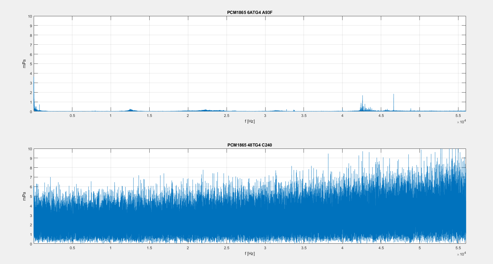
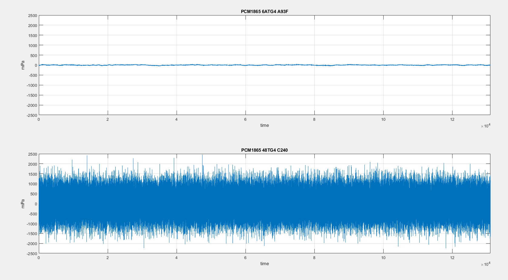
I have two types of PCM series 6ATG4 A93F and 48TG4 C240. The problem is that the noise level is dramatically higher in 48TG4 C240. I compare the noise with a plot in datasheet, which says that useful signal should be -120dB. I count and 6ATG4 A93F have about -140dB but 48TG4 C240 have -100dB which have significant impact on received data. I attach a time course and fft of these two types of PCM. These two elements were on the same PCB board and the same software configuration.
Best regards,
Konrad Koperek
