This thread has been locked.

If you have a related question, please click the "Ask a related question" button in the top right corner. The newly created question will be automatically linked to this question.

INA1650: Ground to be connected with coaxial cable

Part Number: INA1650
Other Parts Discussed in Thread: TPD2E007, INA1651EVM,

Hi,

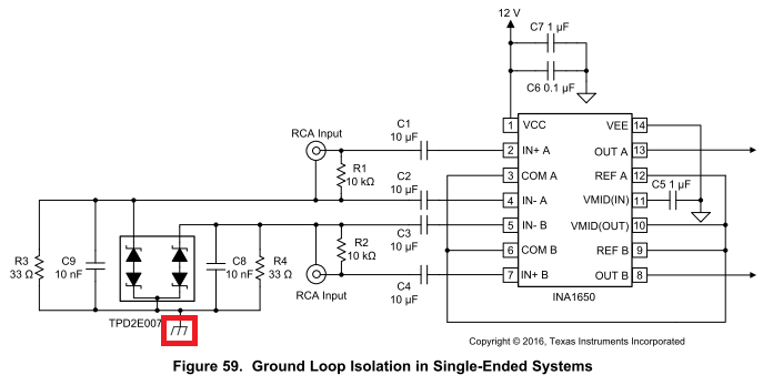
The ground which the coaxial cable is connected is shown by a red frame as below, I would like to confirm just in case, so should this ground be floating to isolate VEE if 0V is supplied to VEE ?
In addition, the following R3, R4, C8, C9 and TPD2E007 aren't mounted on INA1650EVM and INA1651EVM, so could you please tell me that reason ?

Best regards,
Kato

  • Kato-san,

    Please see my replies.

    The ground which the coaxial cable is connected is shown by a red frame as below, I would like to confirm just in case, so should this ground be floating to isolate VEE if 0V is supplied to VEE ?

    The ground in the red box is referred to as the chassis ground while the VEE ground connection is the power supply common. They are not intended to be connected together in this application. Having separate ground keeps the low-level input currents from sharing the same return path with the power supply currents. That helps minimize noise and hum that could otherwise make its way into the INA1650 input circuits.

    In addition, the following R3, R4, C8, C9 and TPD2E007 aren't mounted on INA1650EVM and INA1651EVM, so could you please tell me that reason ?

    Yes, it appears that the INA1650 EVM was not designed to take advantage of the ground loop isolation circuit depicted in figure 59. The reason is not know to me.

    Regards, Thomas

    Precision Amplifiers Applications Engineering

  • Hi Thomas-san,

    Thank you for the explanation.

    I have additional questions, so could you please give me your advice about the following questions ?

    Q1.
    Are there any concerns if when there is a potential difference between chassis ground(red box) and the power supply common(VEE) on the above schematic ?
    e.g. : The capacitors(C1, C2, C3 and C4) should be with High rated voltage.

    Q2.
    Are there any concerns on the above schematic due to usage conditions ?

    Q3.
    Should the ground loop isolation circuit be applied as well if using INA1650 as the differential line receiver like figure 58 which is mentioned on page 25 of INA1650 data sheet ?

    Best regards,
    Kato

  • Kato-san,

    I have additional questions, so could you please give me your advice about the following questions ?

    Q1.

    Are there any concerns if when there is a potential difference between chassis ground(red box) and the power supply common(VEE) on the above schematic ?

    e.g. : The capacitors(C1, C2, C3 and C4) should be with High rated voltage.

    Certainly these capacitors must be designated to withstand whatever potential difference might exist between the two different grounds, plus the signal levels. I don't expect that in most applications that the two ground will be separated by a large voltage, but that needs to be verified.

    Q2.

    Are there any concerns on the above schematic due to usage conditions ?

    The responsibility of assuring that the design is safe in usage lies solely upon the systems designer.

    Q3.

    Should the ground loop isolation circuit be applied as well if using INA1650 as the differential line receiver like figure 58 which is mentioned on page 25 of INA1650 data sheet ?

    It does appear that the concept can be applied to a differential input XLR circuit such as that in Fig. 58. It would be a matter of configuring R3, R4, C8, C9 networks with each INA1650 differential input pair.

    Regards, Thomas

    Precision Amplifiers Applications Engineering

  • Hi Thomas-san,

    Thank you for your prompt reply.

    I understood and will contact you if I have additional questions from our customer.

    Best regards,
    Kato