This thread has been locked.

If you have a related question, please click the "Ask a related question" button in the top right corner. The newly created question will be automatically linked to this question.

TAS2505: Connecting the audio amp to CC3220

Part Number: TAS2505


Hi, guys. I'm trying to create a custom PCB that uses the CC3320SF and TAS2505.

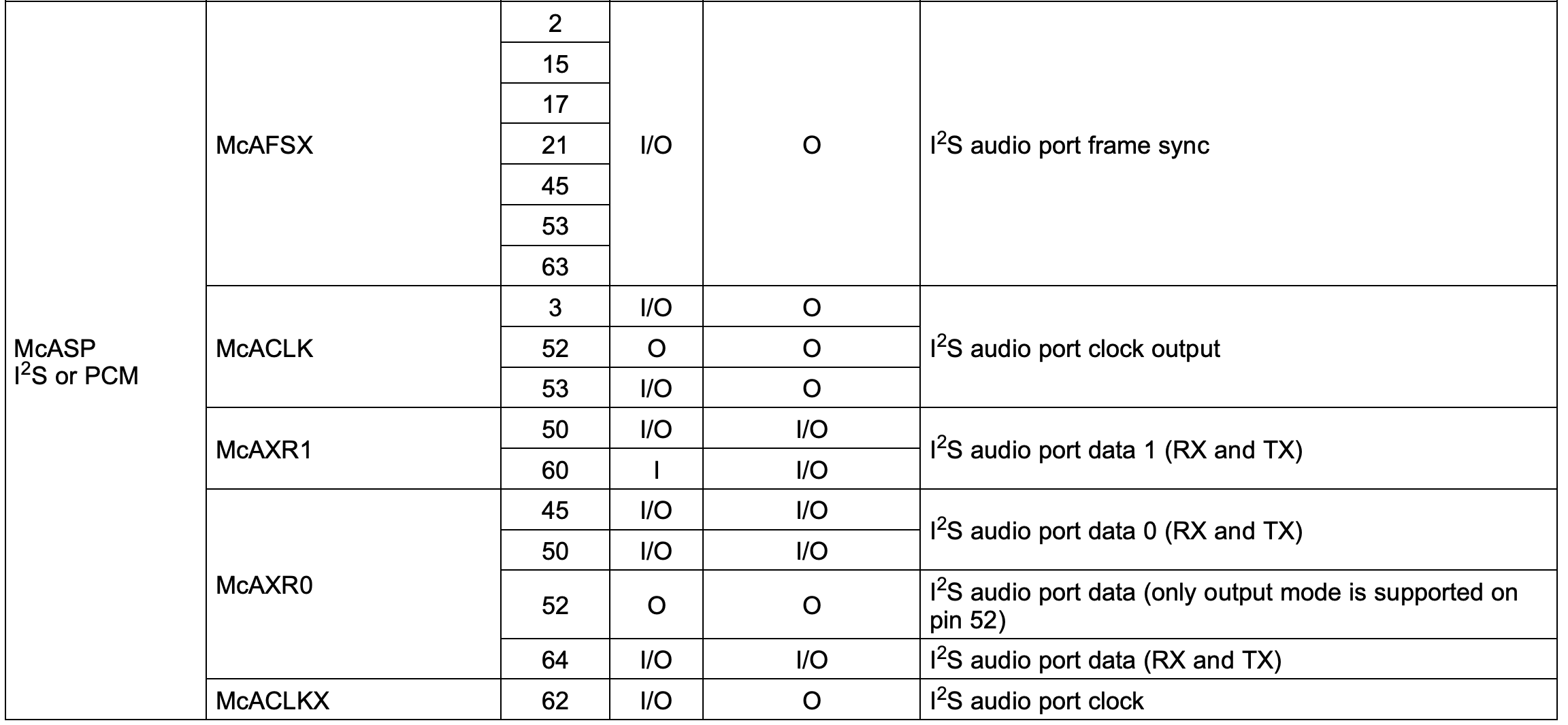
Considering CC3220's pinouts,

What pins should I connect between them? (ex.McACLKX 64 - MCLK)

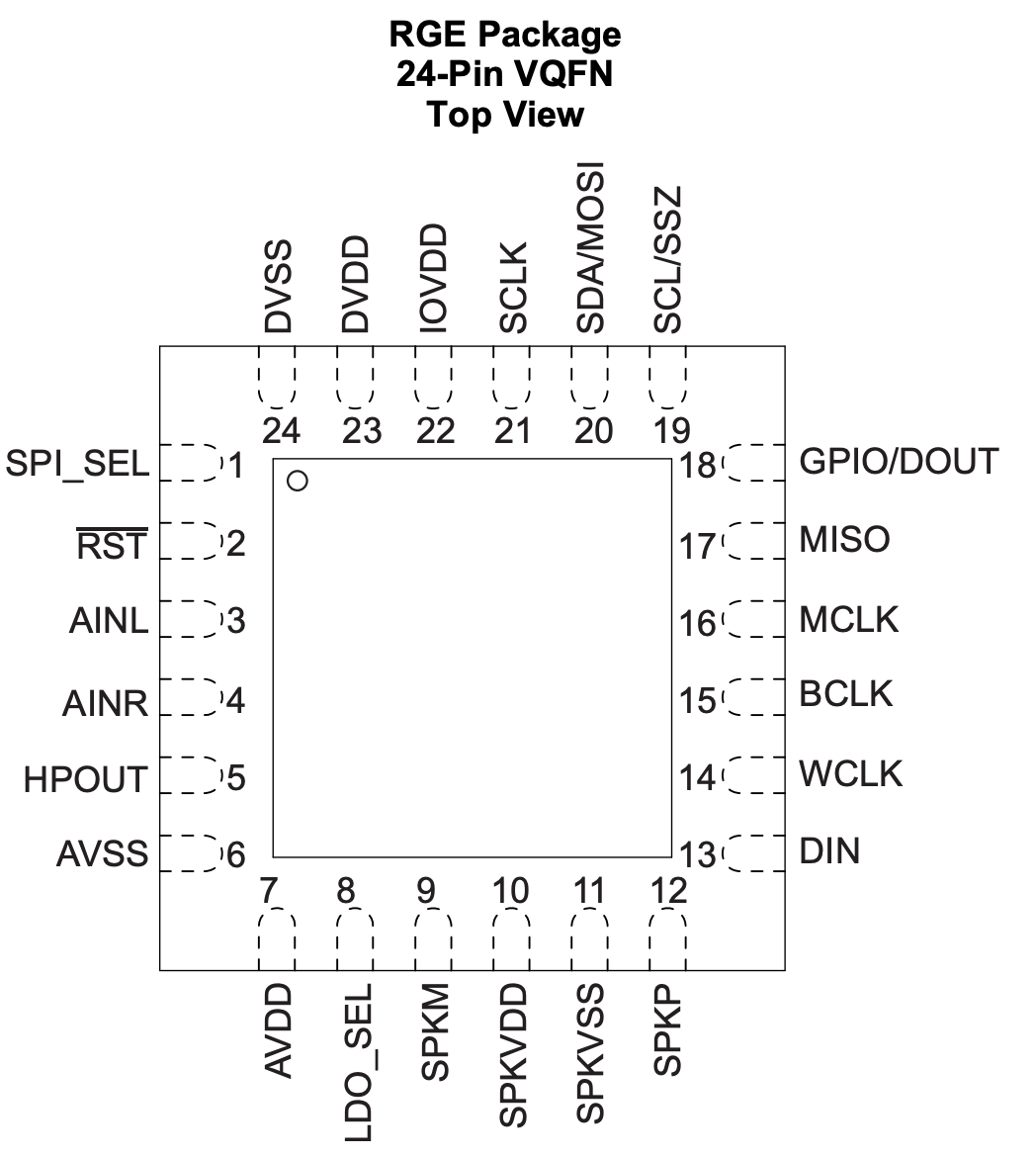
I'm trying to send and play WAV file data via I2S and I will be using SPI for configuring the TAS2505's registers.

The MCLK is most confusing for me. When I used other vendor's device,

I only used BCLK, LRCLK with the Raspberry Pi so I'm having trouble here. Thanks for your help.

  •  Hi, David,

    When a controller is connected to the TAS2505, it is always important to ensure that all serial data interface and control lines are correctly connected from the controller to the TAS2505.

    The control lines can be SPI or I2C lines. These lines will be necessary to read and write the registers of the TAS2505.

    In case of the serial data interface lines, you would need a device that supports I2S (or similar) protocol. At least, you would need of the word clock (WCLK) or frame clock, which determines the word or channel (usually left or right channel data). Then, the bit clock (BCLK) is required to send the bits per channel. Finally, the data lines DIN and DOUT, which will be sending the data to be sampled.

    The MCLK is only required for cases where the BCLK and WCLK cannot be generated from an external controller. The TAS2505 has the capability to work in slave (BCLK and WCLK configured as inputs) or master mode (BCLK and WCLK configured as outputs and generated from the MCLK).

    If your controller has the capability to send BCLK and WCLK clock signals to the TAS2505, there won't be need to use a MCLK. MCLK pin can be left floated.

    Please let me know if you have additional questions or comments on this.

    Best regards,
    Luis Fernando Rodríguez S.

  • Thanks, Luis.

    Also,

    - 13 DIN: Audio Serial Data Bus Input Data

    - 18 GPIO/DOUT: GPIO / Audio Serial Bus Output

    - 5 HPOUT: Headphone and Lineout Driver Output

    - 3 AINL: Analog single-ended line left input

    - 4 AINR: Analog single-ended line right input

    - 12 SPKP: Class-D speaker driver noninverting output

    - 9 SPKM: Class-D speaker driver inverting output

    Q0. I'm only using an 8-ohm speaker, which has 2 leads; + red /- black

    Should I connect + to SPKP and - to SPKM?

    Q1. I don't use the analog line and the headphone.

    Should I just connect AINL, AINR, HPOUT to GND/0V?

    Also, this microcontroller has WCLK and BCLK, so can leave MCLK not connected, right?

    Q2. I'm sending WAV file output.

    After connecting WCLK and BCLK, the DIN and DOUT are left.

    Since this is a speaker I have to connect this SDOUT to DIN, right?

    Q3. Since this is not a microphone, I connect nothing to DOUT or GND to DOUT?

    This microcontroller does have a SDIN pin, but I have no clue what data will go into SDIN when using the TAS2505.

    Q4. Should the exposed pad be connected to GND?

    Q5. Lastly, I heard that the PCM format is similar to a WAV file. If the output is a PCM format, can I still use TAS2505?

  • Hi, David,

    Q0. I'm only using an 8-ohm speaker, which has 2 leads; + red /- black. Should I connect + to SPKP and - to SPKM?

    Actually, you can connect the speaker wires to any of these SPK outputs. There's no difference in the speaker behavior if the red and black connectors are routed to either SPKP or SPKM.

    Q2. I'm sending WAV file output. After connecting WCLK and BCLK, the DIN and DOUT are left. Since this is a speaker I have to connect this SDOUT to DIN, right?

    You are right. The audio data must be sent from the microcontroller SDOUT pin to the TAS2505 DIN pin.

    Q3. Since this is not a microphone, I connect nothing to DOUT or GND to DOUT? This microcontroller does have a SDIN pin, but I have no clue what data will go into SDIN when using the TAS2505.

    DOUT can be left floated in this case. In this case, the TAS2505 DOUT pin can be used if you require a loopback function. You may configure the DOUT pin in order to send the DIN data to the DOUT pin. This can be used for analysis or evaluation purposes. Just to ensure that the microcontroller is sending the data as expected. If this function is not required, you may leave the DOUT pin floated.

    Q4. Lastly, I heard that the PCM format is similar to a WAV file. If the output is a PCM format, can I still use TAS2505?

    Yes, you can. The WAV format is similar to the audio serial protocols that the TAS2505 supports. I would say that it is more similar to the I2S mode. However, for cases where you need a particular data protocol, the TAS2505 has the capability to modify the serial interface. You may add offset in the data lines, configure the clock polarity and even adjust the data length. This flexibility allows the TAS2505 to accept even non-standard protocols if required.

    Best regards,
    Luis Fernando Rodríguez S.

  • A few minor things before closing this;

    - Q0. Should the exposed pad be connected to GND?

    - Q1. This microcontroller has WCLK and BCLK, so can leave MCLK not connected, right?

    - Q2.  I don't use the analog line and the headphone. Should I just connect AINL, AINR, HPOUT to GND/0V?

  • David,

    Sorry, I forgot to answer your question Q2 (or Q1 in your previous post).

    - Q0. Should the exposed pad be connected to GND?

    Yes, this thermal pad should be connected to GND. Particularly, to analog ground (AVSS, SPKVSS).

    Usually, we recommend to separate the ground planes in our DAC devices due to the delta sigma converter activity. Usually, this kind of converters generates a high-frequency digital noise that could be added to the analog portion of the TAS2505. That's why we suggest to separate the ground planes into analog ground plane (AVSS and SPKVSS) and digital ground plane (DVSS). Both planes must be connected through 0-ohm resistors (at least one resistor). This practice is always suggested to prevent digital noise in the analog portion.

    - Q1. This microcontroller has WCLK and BCLK, so can leave MCLK not connected, right? 

    You are right. MCLK can be left floated is it is not required to generate WCLK or BCLK. Basically, it is only required for the master mode.

    - Q2.  I don't use the analog line and the headphone. Should I just connect AINL, AINR, HPOUT to GND/0V? 

    Only analog inputs should be AC-coupled to GND. A 0.1uF to 0.47uF capacitor per input is enough for this. HPOUT must be left floated if it is not used.

    Best regards,
    Luis Fernando Rodríguez S.

  • Wow, thanks for your kind reply.

    Luis Fernando Rodriguez S. said:
    we suggest to separate the ground planes into analog ground plane (AVSS and SPKVSS) and digital ground plane (DVSS). Both planes must be connected through 0-ohm resistors (at least one resistor). This practice is always suggested to prevent digital noise in the analog portion.

    Luis Fernando Rodriguez S. said:
    Only analog inputs should be AC-coupled to GND. A 0.1uF to 0.47uF capacitor per input is enough for this.

    You mean like this?

    This is powered by a battery and I'm using 3.3V buck converter output.

  • David,

    Almost! I just have one suggestion for the digital ground plane.

    The digital activity and digital supplies pins (IOVDD and DVDD) must be referenced to DVSS. In your schematic, DVDD and IOVDD are referenced to GND, which is the analog ground plane. I would suggest to add another ground reference as digital GND and connect the DVDD and IOVDD capacitors to this new reference instead of GND (analog ground).

    Please take a look at this layout example for details. This is an ADC device that also requires of this digital and analog ground planes separation for noise prevention. Notice that both ground planes are joined with two 0-ohms resistors (or two PCB traces).

    http://www.ti.com/lit/ds/slas553b/slas553b.pdf#page=83

    Best regards,
    Luis Fernando Rodríguez S.