A related question is a question created from another question. When the related question is created, it will be automatically linked to the original question.
If you have a related question, please click the "Ask a related question" button in the top right corner. The newly created question will be automatically linked to this question.
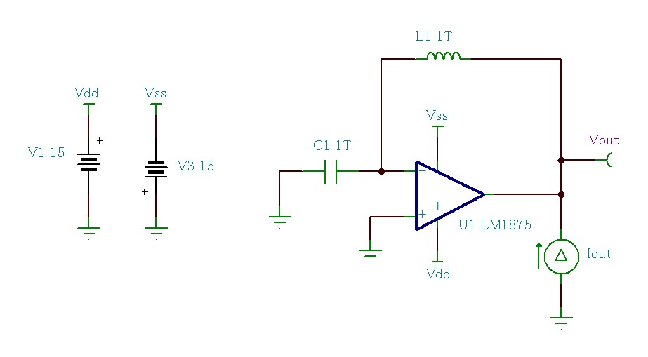
LM1875: Frequency characteristics of output impedance
In our customer's applications, LM1875 drives heavy inductive loads. And LM1875 is used with high gain of about 30 dB. So, in order to study the behavior of the output, the customer seems to want to know the frequency characteristics of the output impedance.
I think that the characteristics of the output impedance can be estimated by TINA-TI simulation. Do the parameters match the real IC?
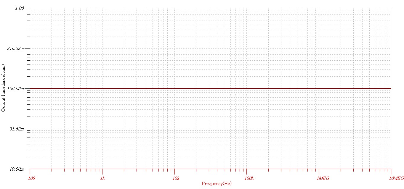
Looking at this result, I think that is not normal.
Checking the macro of the LM1875 simulation model, it seems that there are no parameters related to output impedance. Do you have simulation models regarding output impedance for LM1875?
For reference, the OPA2377 simulation model seems to contain the output impedance model as follows.
************************************************** ****************************** * * BEGIN MODEL OPA 2377 * THIS MODEL IS APPLICABLE TO OPA 377 OPA 2 377 OPA 4 377 * MODEL FEATURES INCLUDE OUTPUT SWING, OUTPUT CURRENT * THROUGH THE SUPPLY RAILS, RAIL-TO-RAIL OUTPUT STAGE, * OUTPUT CURRENT LIMIT, OPEN LOOP GAIN AND PHASE WITH * RL AND CL EFFECTS, SETTLING TIME, OVERLOAD RECOVERY * TIME, SEPERATE COMMON MODE RESOURCES WITH FREQUENCY * EFFECTS FOR EACH INPUT REGION, OUTPUT IMPEDANCE VS * FREQUENCY, POWER SUPPLY REJECTION WITH FREQUENCY * EFFECTS, INPUT VOLTAGE NOISE WITH 1 / F, INPUT CURRENT * NOISE, INPUT BIAS CURRENT WITH TEMPERATURE EFFECTS, * INPUT IMPEDANCE, INPUT COMMON MODE RANGE, SEPERATE * INPUT OFFSET FOR EACH INPUT REGION, OFFSET TEMPERA- * TURE EFFECTS, AND QUIESCENT CURRENT VS VOLTAGE AND * TEMPERATURE. * MODEL TEMP RANGE IS -40 TO +125 DEG C. * NOTE THAT MODEL IS FUNCTIONAL OVER THIS RANGE BUT * NOT ALL PARAMETERS TRACK THOSE OF THE REAL PART.
Different TINA model has various precision. Based on your simulation result, LM1875 TINA model does not take output impedance into consideration.
Our BU side also does have limited data with this old device. So is it possible to use LM1875 sample to measure the output impedance curve by yourself?


