This thread has been locked.

If you have a related question, please click the "Ask a related question" button in the top right corner. The newly created question will be automatically linked to this question.

DRV595: Is the diagnostic related to temperature?

Part Number: DRV595

Dear team,

Here is a question about DRV595.

Our customer use this chip in a TEC application. When they do the low temperature test, they found that if they put the chip(DRV595) and the TEC element into the cold temperature(about -30 °C) together, the chip will reporting fault after about 3 to 5 minutes. If they put the TEC element into the cold temperature but put the chip in room temperature, the chip will report fault only after about 80 seconds. It seems that the temperature of our chip effect the diagnostic function. I will follow this issue and ask customer do more test to confirm what cause the fault.

My question is, regardless of the cause of the fault, is the diagnostic feature related to the temperature?

I will update this issue if I get more information. please kindly help us clear up this confusion first.

B&R

Lijia Zhu

  • Hi Lijia,

    First of all, I think it's necessary to check what fault was triggered.

    Most protections integrated on our IC need to monitor the working condition and decide when to act. For example, over current protection monitors the current flowing through the device and if the current exceeds the threshold, protection circuit will take effect. I would say temperature could have very slight impact on the thresholds, but I don't think the problem you described was related to this slightly change.

  • Hi Hao,

    Here is the update of this issue.

    1.First of all, the fault is not a latched fault, this must a over current or over temperature fault.

    2.Secondly, when the chip is normal working, the temperature is about 40 °C, so it must be a over current fault.

    3.The power supply to the chip is about 12V and 2.5A. But the voltage and current across the load is about 10.7V and 2.1A. However, there must be 11V across the load so that the load can generate enough heat.

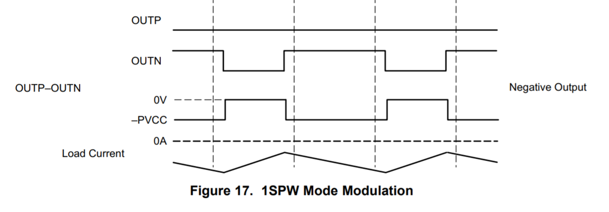
    4.At the same time, it can be observed that the PWM output signal (OUTN pin) is a straight line, and the mode used is shown in the figure below.

    My question is, for the phenomenon mentioned in the third point, is it because the duty cycle of the PWM has reached the upper limit so that the voltage so that the voltage can't reach a higher level? Does the PWM have an upper limit on the duty cycle?

  • Hi Lijia,

    Single output switching is normal operation for 1SPW modulation, which helps to improve the efficiency.

    Have you tried to increase the input signal level? And also the PVDD level? Let's check if there is any voltage clip here.

    Noticed you have an email to me, we can move this offline and have further communication by email. Thanks!

    Regards,

    Hao