This thread has been locked.

If you have a related question, please click the "Ask a related question" button in the top right corner. The newly created question will be automatically linked to this question.

TLV320DAC3120: How to program the TI with given settings / clocks to output to speaker

Part Number: TLV320DAC3120

Hello

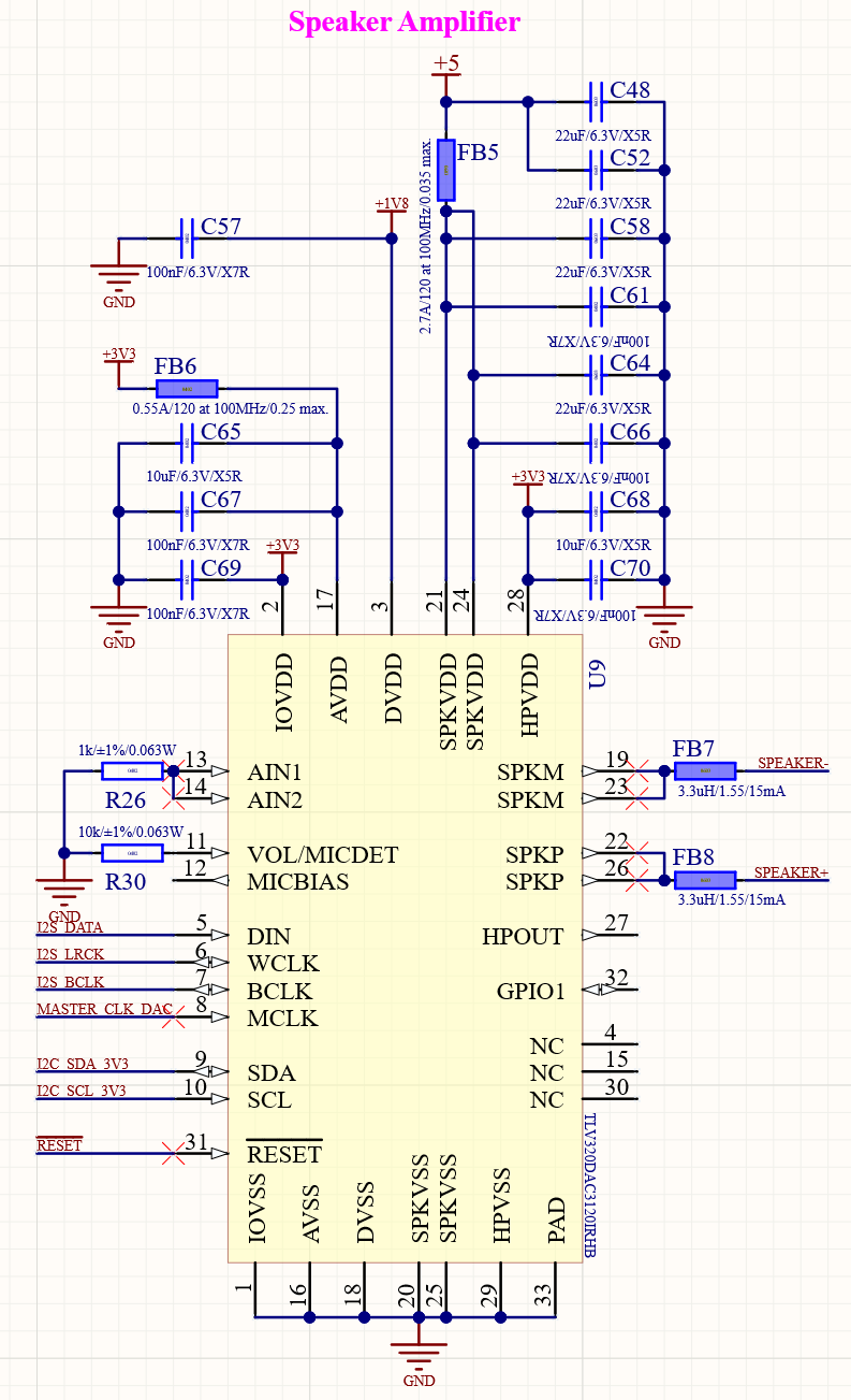
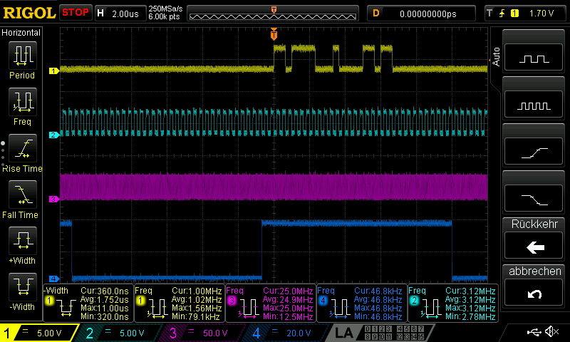
i'm using the TI TLV320DAC3120 and the XMOS XVF3100. The i2c communication works but i'm not getting anything out of the ti to a speaker like with the dev board TI ACEV-1B. I guess i have to set up the clocks... The WCLK is 15.6 kHz, the BCLK is 1 MHz and the MCLK is 24 MHz. What do i have to set up and how to calculate the correct values?

The output from xmos is through i2s and do i have to set up there anything in the ti ?

Thanks in advance

twittich

  • Hi, Thorben,

    This should be related to the registers configuration and the device circuit could be also involved. Could you share your registers settings and the TLV320DAC3120 schematic portion, please? This would give us a better approach to this issue.

    Thank you.

    Best regards,
    Luis Fernando Rodríguez S.

  • Thank you for this response too :) .

    Up to now i have no specific settings. Just want to use the i2s input and output at speaker. The beep is working. The schematic is attached. Which registers do i have to set for getting the output ?

    Regards twittich

  • Hi, Twittich,

    Just to confirm, is the MCLK connected to the circuit? If so, you may use the registers script below:

    DAC3120_Init_File_II.txt
    ###############################################
    # Software Reset
    ###############################################
    #
    # Select Page 0
    w 30 00 00
    #
    # Initialize the device through software reset
    w 30 01 01
    #
    ###############################################
    
    ###############################################
    # Clock and Interface Settings
    # ---------------------------------------------
    # The codec receives: MCLK = 12 MHz,
    # BLCK = 1 MHz, WCLK = 15.6 kHz
    ###############################################
    #
    # Select Page 0
    w 30 00 00
    #
    # PLL_clkin = MCLK, codec_clkin = PLL_CLK,
    # PLL on, P=1, R=1, J=6, D=9888 (0x26A0)
    w 30 04 03 91 06 26 A0
    #
    # NDAC = 3, MDAC = 14, dividers powered on
    w 30 0b 83 8e
    #
    # DOSR = 128
    w 30 0D 00 80
    #
    # NADC = 3, MADC = 14, dividers powered on
    w 30 12 83 8e
    #
    # AOSR = 128
    w 30 14 80
    #
    ###############################################
    
    ###############################################
    # Signal Processing Settings
    ###############################################
    #
    # Select Page 0
    w 30 00 00
    #
    # PRB_P5, PRB_R5
    w 30 3c 05 05
    #
    # Enable Adaptive Filtering
    w 30 00 08
    w 30 01 04
    #
    ###############################################
    
    ##########################################
    # Configure Class-D Output
    ##########################################
    #
    # Switch to Page 1
    w 30 00 01
    #
    # CM = 1.65V
    w 30 1f 14
    #
    # Unmute Class-D (6dB)
    w 30 2a 04
    # Unmute Class-D (12dB)
    # w 30 2a 0c
    # Unmute Class-D (18dB)
    # w 30 2a 14
    # Unmute Class-D (24dB)
    # w 30 2a 1c
    #
    # Power-up Class-D driver
    w 30 20 86
    #
    # Route Analog Volume Control to Class-D Driver, 0dB
    w 30 26 80
    #
    ##########################################
    
    ##########################################
    # Configure DAC Channel
    ##########################################
    #
    # Switch to Page 1
    w 30 00 01
    #
    # DAC routed to Mixer Amplifier
    w 30 23 40
    #
    # Switch to Page 0
    w 30 00 00
    #
    # Powerup DAC, DAC => LI2S, soft-step disable
    w 30 3f 96
    #
    # Unmute DAC, 0dB
    w 30 40 04 00
    #
    ##########################################

    It is an example of a configuration I2S to speaker. I modified the clock values accordingly to the clock values you provided.

    I hope this helps you. Please let me know if you have additional questions or comments on this.

    Best regards,
    Luis Fernando Rodríguez S.

  • Hi, Twittich,

    One additional comment, the registers settings are in format w 30 xx yy.

    w (I2C write command) 30 (I2C address in hex format) xx (register address in hex format) yy (register data in hex format).

    Best regards,
    Luis Fernando Rodríguez S.

  • Good morning,

    thank you very much. i'll test it and let you know if it works. Yes the MCLK is connected and the i2c communication (write and readback) is working already.

    Regards twittich

  • I have configured it with these settings but there is no output from the speaker even no roaring/buzzing. With the beep script (beep works) the volume of buzzing was changing when i changed the volume in windows.

    https://e2e.ti.com/cfs-file/__key/communityserver-discussions-components-files/6/DAC3120_5F00_Master_5F00_Mode_5F00_Beep_5F00_Generator.txt

    Now there is no signal, checked with oscilator, too.

    Just to confirm, if there is more data in a command its as usual that the register counts up, right ?

    w 30 04 03 91 06 26 A0

    equals

    REGWRITE(0x04,0x03);
    REGWRITE(0x05,0x91);
    REGWRITE(0x06,0x06);
    REGWRITE(0x07,0x26);
    REGWRITE(0x08,0xa0);

    The MCLK is 24 MHz but in the comment is 12 MHz, is the comment not correct or just not changed?  And where do i have to insert delays after reset and somehwere after the pll configuration right ?

    Thank you for your help.

    Regards

    twittich

  • Hi, Twittich,

    Regarding your comment about the I2C command, you are right. When multiple data is written the register address counts up as you correctly mentioned.

    I made a mistake on the PLL configuration, I don't know why I placed MCLK  = 12MHz. Please find attached the correct registers configuration for 24MHz. (Are the BCLK and WCLK values correct?). I also included the delay values in the correct place of the code.

    DAC3120_Init_File_III.txt
    ###############################################
    # Software Reset
    ###############################################
    #
    # Select Page 0
    w 30 00 00
    #
    # Initialize the device through software reset
    w 30 01 01
    #
    # Delay 1ms
    d 1
    #
    ###############################################
    
    ###############################################
    # Clock and Interface Settings
    # ---------------------------------------------
    # The codec receives: MCLK = 24 MHz,
    # BLCK = 1 MHz, WCLK = 15.6 kHz
    ###############################################
    #
    # Select Page 0
    w 30 00 00
    #
    # PLL_clkin = MCLK, codec_clkin = PLL_CLK,
    # PLL on, P=2, R=1, J=6, D=9888 (0x26A0)
    w 30 04 03 A1 06 26 A0
    #
    # NDAC = 3, MDAC = 14, dividers powered on
    w 30 0b 83 8e
    #
    # DOSR = 128
    w 30 0D 00 80
    #
    # NADC = 3, MADC = 14, dividers powered on
    w 30 12 83 8e
    #
    # AOSR = 128
    w 30 14 80
    #
    # Delay 10 ms
    d 10
    #
    ###############################################
    
    ###############################################
    # Signal Processing Settings
    ###############################################
    #
    # Select Page 0
    w 30 00 00
    #
    # PRB_P5, PRB_R5
    w 30 3c 05 05
    #
    # Enable Adaptive Filtering
    w 30 00 08
    w 30 01 04
    #
    ###############################################
    
    ##########################################
    # Configure Class-D Output
    ##########################################
    #
    # Switch to Page 1
    w 30 00 01
    #
    # CM = 1.65V
    w 30 1f 14
    #
    # Unmute Class-D (6dB)
    w 30 2a 04
    # Unmute Class-D (12dB)
    # w 30 2a 0c
    # Unmute Class-D (18dB)
    # w 30 2a 14
    # Unmute Class-D (24dB)
    # w 30 2a 1c
    #
    # Power-up Class-D driver
    w 30 20 86
    #
    # Route Analog Volume Control to Class-D Driver, 0dB
    w 30 26 80
    #
    ##########################################
    
    ##########################################
    # Configure DAC Channel
    ##########################################
    #
    # Switch to Page 1
    w 30 00 01
    #
    # DAC routed to Mixer Amplifier
    w 30 23 40
    #
    # Switch to Page 0
    w 30 00 00
    #
    # Powerup DAC, DAC => LI2S, soft-step disable
    w 30 3f 96
    #
    # Unmute DAC, 0dB
    w 30 40 04 00
    #
    ##########################################

    Please let me know if you have any observation (if you could get any output, if there's Class-D activity, etc.).

    Thank you.

    Best regards,
    Luis Fernando Rodríguez S.

  • Hi Thank you very much. Just the p value had to be changed ;-) .

    But there is still silence. I have to go again through the beep example there must be a setting partial correct so that the buzzing is coming.

    --> Do i have to pay attention to anything from the source of i2s ?

    How do you calculate that if i go through the Clock distributuion tree i'm getting strange values with these.

    The MCLK is defined as PLL_CLKIN means that PLL_CLK is( MCLK * (R * J.D)/P )

    24000000 * (1 * 6.9888) / 2

    = CODEC_CLKIN = PLL_CLK

    ( 24000000 * (1 * 6.9888) / 2) / 3

    = DAC_CLK

    ((24000000 * (1 * 6.9888) / 2)/3)/14

    = DAC_MOD_CLK

    (((24000000 * (1 * 6.9888) / 2)/3)/14)/128

    = DAC_fs this is the word clock right?   I just found a calculation mistake so i edited this...

    --> Do i have to set up the bitclock ?

    bdiv_clkin = dac_clk which is by the calculation above 27955200

    and set the n val to 27 to get nearly 1 Mhz ....

  • Hi, Twittich,

    Your calculation is correct, the sample rate is defined by the WCLK, that's why I adjusted the PLL values to reach 15.6 KHz.

    There’s no need to configure anything in the registers regarding the BLCK unless you want to generate it from the TLV320DAC3120. You just need to ensure that the BCLK = (data lenght) x (number of channels) x WCLK. At least, BCLK should be BCLK = (16) x (2) x (15.6KHz) ≈ 0.5MHz. So, 1MHz works fine too.

    Regarding the output, is there any activity on the Class-D amplifier? Are the Class-D outputs in phase? If so, I think there should be something wrong on the I2S data. Could you verify that the data is being sent correctly please?

    Thank you.

    Best regards,

    Luis Fernando Rodríguez S.

  • Hello

    i meassured all again and the values were incorrect.

    If i check each separate then LRCLK = 48 kHz, BCLK=3 MHz and MCLK=24 MHz

    So i changed the following register values to:

    P=2, R=1, J=7, D=6800, NDAC=3, MDAC=5

    Do i have to change anything else?

    and is it correct to write these registers ( page 0 reg 18 and 19 ) because in the datasheet is written they are reserved and don't write?

    Yellow: DIN, Pink: MCLK, Dark blue: WCLK, Light blue: BCLK

    And if meassure on SPK+ looks always same, if music is playing or not:

  • Hi, Twittich,

    Thank you for providing the details in the pictures.

    The PLL configuration is correct for the clocks that you are using. Regarding the data from DIN, it seems that you are sending the data through the right channel (see I2C configuration for details: http://www.ti.com/lit/ds/symlink/tlv320dac3120.pdf#page=51 ).

    I would suggest to change the data to the left channel or modify the page 0 / register 63 (0x3F) to receive the data from the right channel:

    http://www.ti.com/lit/ds/symlink/tlv320dac3120.pdf#page=67

    Please let me know if this works and if you have additional observations.

    Best regards,
    Luis Fernando Rodríguez S.

  • Thank you very much. I had to change the cahnnel. :-)