Are there any known issues or specific design considerations already posted somewhere for the DIT4096 TXP/TXN output stage?
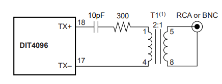
I have a design implemented that follows data sheet for all connections including VDD/VIO, bypassing and TXP/TXN connection to a scientific conversion xfmr. Everything works great, all signals look good. The problem is fairly significant EMI noise is generated (only) when the DIT4096 TXP/TXN outputs are driving current into (known good) AES receiver. The EMI noise is corrupting board ground/supplies and impacting RF performance of a nearby Cypress CYBT3430326 BT module located on same board. The TXP/TXN pin output signals look good except ~1V overshoot (symmetrical both pos/neg outputs).The AES signals on the wire look good except can see the overshoot and some small cable reflections. The design is running at 48khz sample rate = 6MB/s data rate on the AES (RS422) signal.
I noticed several similar parts from other mfrs have internal output impedance about 25 ohms for each of the TXP/TXN outputs. The DIT 4096 does not have this internal impedance. Presumably the other mfrs did this to tame the outputs for reduced EMI. Wondering if anyone has experienced similar issues with DIT4096 and what they did to resolve.
Regards,
Scott Potosky