This thread has been locked.

If you have a related question, please click the "Ask a related question" button in the top right corner. The newly created question will be automatically linked to this question.

TPA3250: TPA3250 analog inputs bias and operation at DC and low frequencies

Part Number: TPA3250
Other Parts Discussed in Thread: DRV201, DRV2510-Q1, DRV2511-Q1, TPS68470, DRV8850

I'd like to use TPA3250 in PBTL configuration to drive a voice coil actuator. The required frequency is 0-40 Hz. To drive it at 0 Hz I would have to remove DC blocking capacitors at the amplifier inputs.

Are the IC analog inputs internally biased? If yes, to what voltage?
Can the amplifier inputs be biased with 2.5V?

In general, do you see any additional problems for the IC not to work at DC and very low frequencies?

  • Hi,

    Yes, it's internally biased. It should be 1/2AVDD, ~ 3.9V.

    Regards,

    Hao

  • Thank you for your reply,

    Will the part-work if we remove DC blocking capacitors and apply a common-mode signal of 2.5V to Input A and B?

  • Hi Stan.V,

    Do you want to use TPA3250 to output DC voltage? If yes, TPA3250 does have DC protection, which doesn't allow to output DC voltage.

  • I'm planning on using the amplifier in PBTL mode. So, luckily DC protection is disabled. My final goal is to make a voice coil actuator oscillate around a small offset of the center. I was hoping to apply a small DC bias voltage to one of the inputs, let's say Input A, and apply the signal to Input B. Do you think this configuration would be feasible?

  • Hi Stan,

    I'm a little confused with what your describing.  The TPA3250 uses differential inputs. Are you saying you'd apply a small DC bias voltage to only Input A and then an analog signal into Input B? 

    While it might be possible, we have never validated the device without the DC blocking capacitors so we can't guarantee it's performance. 

    Regards,

    Robert Clifton

  • Actually it looks like applying a small bias to one of the inputs worked. 
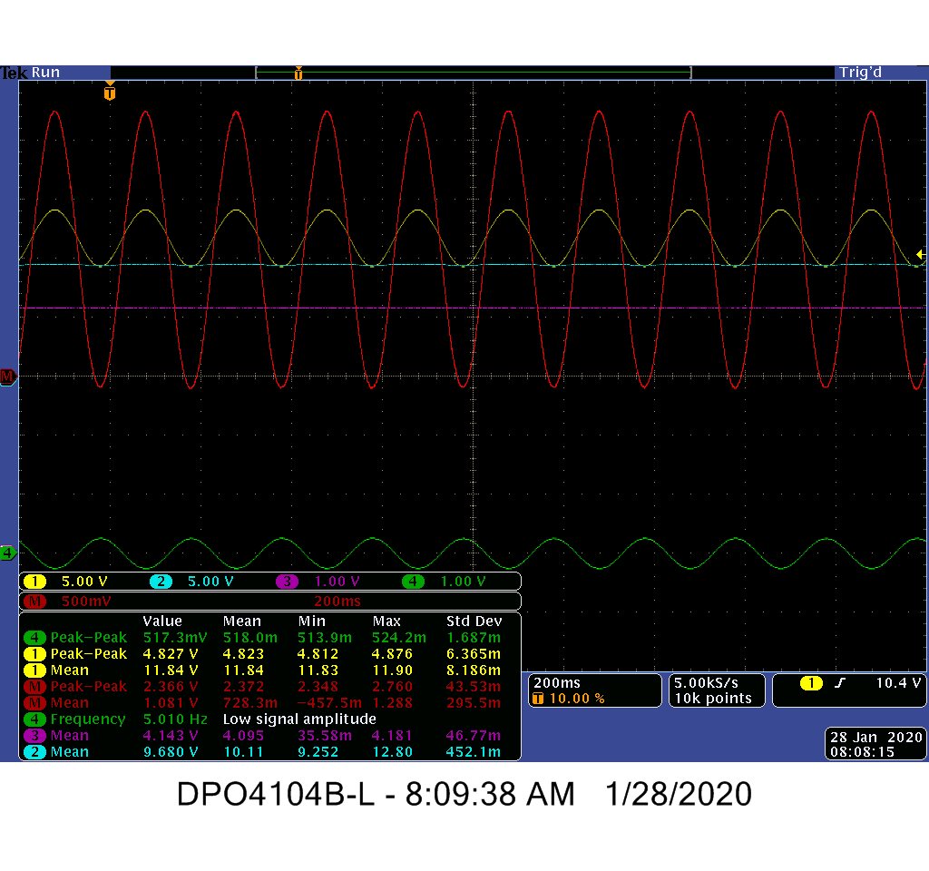
    I used the EVM configured in PBTL mode for the experiments. I disconnected Input B and measured the internal bias voltage at the input, which was around 3.9V

    Then I connected an external 4.1V to input B, which is 0.2V higher than a bias. This bias voltage is channel 3/purple oscilloscope trace on the screenshot. 

    The signal was fed to Input A using DC blocking capacitors of higher value, to allow low frequency 5 Hz input signal. (Channel 4/green trace)

    Channels 1 (yellow) and 2 (blue) were connected to the output of the speaker/solenoid coil.

    0.2V biased caused the resulting mean value of the output signal ( red trace, which is the math function of channels (1-2)/2) move from 0 to 1 volt. The mean value of 1 volt, corresponds to a gain of 5, which is what I expected.

    Having said so, voice coil movement proportional to the input voltage should be a classical problem for motion control ICs. Is there anyone in the motion control group who can point me to a proper motor control IC  that might perform the function?

  • Hello Stan, 

    Thanks for sharing this information in the forum for the understanding of everyone. 

    I will now close this thread, please begin a new thread for your other questions. (This thread can be linked to as well.) 

    All the best, 

    Carolina

  • Hi Stan,

    Let me try getting you in contact with the motor drives team to see if they would know. 

    Best Regards,

    Robert Clifton

  • Hi Stan,

    The motor driver devices do not have an analog input.

    The devices typically have a PWM input (either Phase/Enable or IN1/IN2) to control the H-Bridges outputs.

    A quick search of products using "site:www.ti.com voice coil motor driver" identified a several devices, although the voltage, current, and features may not meet your needs:

    DRV201

    DRV2510-Q1

    DRV2511-Q1

    TPS68470

    DRV8850

    If any of these might work, please let us know and we will contact the team responsible