This thread has been locked.

If you have a related question, please click the "Ask a related question" button in the top right corner. The newly created question will be automatically linked to this question.

OPA1611: Finding Open-loop transferfunctions of opamps and amplifiers

Part Number: OPA1611
Other Parts Discussed in Thread: LME49600, LME49990, OPA1612,

Hi,

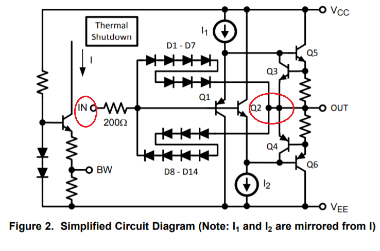
I am currently working on a high performance headphone amplifier. I have found a schematic online (I added the schematic as an attachment). In the schematic it can be seen that the LME49990 and the LME49600 are used with global feedback.
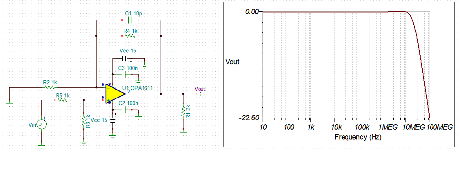
Unfortunately the LME49990 has been discontinued (shame for such a nice opamp) for a while. The recommended replacement for this amplifier is the OPA1611 or OPA1612(same but 2 in one package).

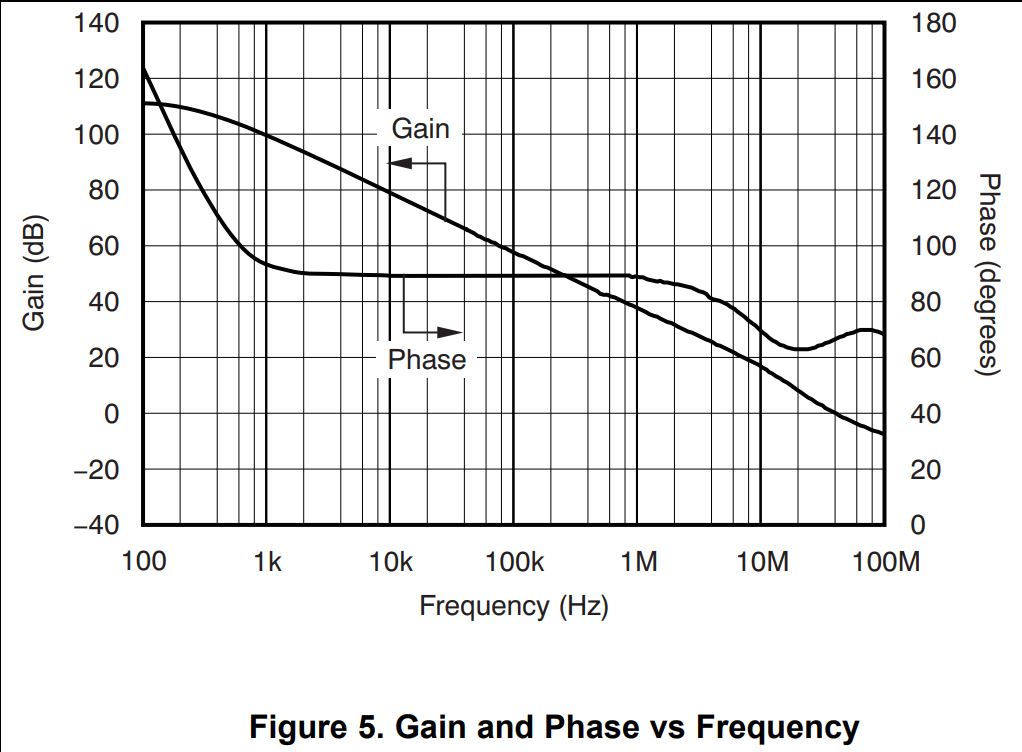
Since global feedback is applied it is critical for performance and stability to know where the poles and zeroes are placed. I know that the combination of the LME49990 and LME49600 is stable, but I do not know where their poles and zeroes are placed. I also do not know where they are in the OPA1611/OPA1612. This makes it very hard for me to design an amplifier. Sometimes the openloop transferfunction is given in the spice model, but I do not know how to extract that information from the file.

Is there anyway I can find the openloop transferfunction of the OPA1611, the OPA1612, LME49600 and the LME49990 opamps?

Thanks in advance and kind regards,

Hidde 
HDPH BAL.pdf

  • Hi Hidde ,

    LME49600  IC is headphone Buffer. It has a complementary-symmetry Class-AB output driver, see the image below.

    If you look at your attached schematic, The LME49600 output buffer, pin4 is fed back to V- of LME49990 op amp through R9 feedback resistor. Your attached audio schematic is running in closed loop. 

    OPA1611 is an audio op amp and its datasheet specification is comparable to the LME49600 buffer (may be slightly better). OPA1612 is dual package of OPA1611. 

    I think that you want closed loop unity gain op amp characteristics of OPA1611. Please let me know if this is what you are asking. Per your output stage U5-A + A2, you may combine both parts in OPA1611.

    I transferred your feedback resistor values into Tina simulation. The transfer function in the closed loop is Vout/V+ = 1+ R4/R2 = 2, where V+ = 0.5*Vin. Thus Vout/Vin = 1, see the attached Tina Simulation.

    There is a Que at approx. 19.5MHz as is. I compensated the Q by paralleling 10pF capacitor with the R4 feedback resistor, which is 1kHz. Now the feedback circuit should be stable for your audio amplifier. 

    The BW of the OPA1611 is measured at approx. 22.4MHz. I would suggest you may want to lower the BW for your audio application. OPA1611 is falling at a rate of -20dB/decade. The circuit has a phase margin of 65.3 degree. The audio driver should be be stable. 

    /cfs-file/__key/communityserver-discussions-components-files/6/OPA1611_2D00_2-Closed-Loop-03302020.TSC

    The simulation is assumed that OPA1611's output is resistive load. If you can provide me with actual audio load, I will be happy to check the stability for you. 

    Best,

    Raymond

  • Hi there Raymond!

    Thanks for the reply, but I think we are misunderstanding eachother. The output of the LME49600 is fed back into the input of the LME49990 and not to it's own input! I still want to use the LME49600, because it is still commonly available and have no bad experience with it.

    We now have a two stage amplifier with global feedback! I want to analyse it's stability. To analyse the stability I use Matlab with an opamp model ( I design the circuit around it myself). Normally the open loop transfer function of an opamp is A*(Vnoninv - Vinv). A is the gain, Vinv is the voltage at the inverting input of the opamp and Vnoninv is the voltage at the non-inverting input.

    The voltages at the inputs are defined by my design, but the gain is determined by the opamp! There are plots of it in the datasheet. I've attached the Gain and Phase Bode plot of the 1611 as example of what I mean.

    Unfortunately Matlab and many other simulation programs do not understand pictures. I would need some form of mathematical transferfunction. Usually these transfer functions are given in the form:
    G*(an*s^n+.....+a2*s^2+a1*s+a0)/(bn*s^n+.....+b2*s^2+b1*s+b0) or in the form:
    G*((s+an)*.....*(s+a1)*(s+a0)/(s+bn)*.....*(s+b1)*(s+b0))

    With this information I can draw the bode plot myself and model around it by adding my own poles and zeros.

    You also mentioned that it's recommended to lower the bandwidth for audio purposes. This is one of the things I want to adjust, because lowering the gain increases the loopgain at high frequencies (and thus increases the disturbance rejection).

    Kind regards,

    Hidde de Wit


  • Hi Hidde,

    I see what you are asking now. I could not figure out why you are asking for the Open Loop Transfer function, when you have closed loop schematic. You are asking difficult questions, but I will attempt to answer them.

    In open loop control in Op Amp, since Gain is so high, any input will cause the output to rail as you indicated in A(V+ - V-) . In addition, a circuit will not oscillate if it is operating in an open loop condition, even if the circuit has more than one poles (assume you are able to control Gain in an open loop circuit). The oscillation in op amp is resulted from a closed loop feedback, when there are more than one poles are presented in a closed loop system. 

    Enclosed is a video clip talking about poles, zeros and bandwidth in op amp.. 

    https://training.ti.com/ti-precision-labs-op-amps-bandwidth-1?context=1139747-1139745-14685-1138800-13124

    Question:

    Is there anyway I can find the open loop transfer function of the OPA1611, the OPA1612LME49600 and the LME49990 opamps?

    Answer:

    Without having the actual IC schematic, it is difficult to get the exact Op Amp transfer function in an open loop. However, you can estimate the open loop transfer function from the Bode plot. Many op amp's key parameters you can extracted from the datasheet, such as compensation capacitor value, gain and bandwidth, poles, zeros etc.. However, it is difficult to find out the parasitic capacitances that result 2nd, 3rd poles etc. in an op amp.. Once the frequency break points are extracted, you can estimate the Open Loop Transfer function. 

    Since you use Matlab, you may be able to adjust these break out, until  the generated bode plot matches with the real plot in open loop.

    To achieve a closed loop stability in op amp, you want to the op amp frequency response to have a single pole roll off at -20dB/decade. If there are more than one poles in the close loop response, you want to compensate the additional pole with a zero, to achieve -20dB/decade in frequency response. 

    In Figure 5 of OPA1611 datasheet, the Bode plot in open loop is shown, please see the captured image below. 

    Best,

    Raymond

  • Thanks!

    I thought of this way, but I thought it was rather inaccurate. I knew it was hard to acquire the actual poles and zero's if you don't have the actualy schematic. After all it's the whole reason I started wondering how I could do it even at all! 

    Thanks for this solution though, I now know how to proceed my project.

    Kind regards,

    Hidde