This thread has been locked.

If you have a related question, please click the "Ask a related question" button in the top right corner. The newly created question will be automatically linked to this question.

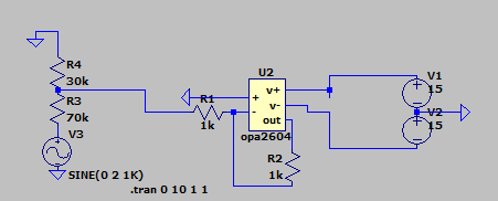
OPA604: Inverting voltage follower problem

Part Number: OPA604
Other Parts Discussed in Thread: LM4562, OPA2604, TL072

Hello, I would like to ask a question about some opamps are not working in my simple voltage follower circuit. I have tried tl072, opa2111kp, opa2604, lm4562, and some other opamps. Only tl072 and opa2111kp working good in my circuit, the others can't provide correct output, and only very loud noise If I listen to the output signal(even if the input is unplugged) . I am quite sure the opamps aren't broken, because I have tried over 10 opamps, and both of them working fine with the headphone amp circuit with Non-inverting amp with 3v/v gain. 

  • Hi Jason,

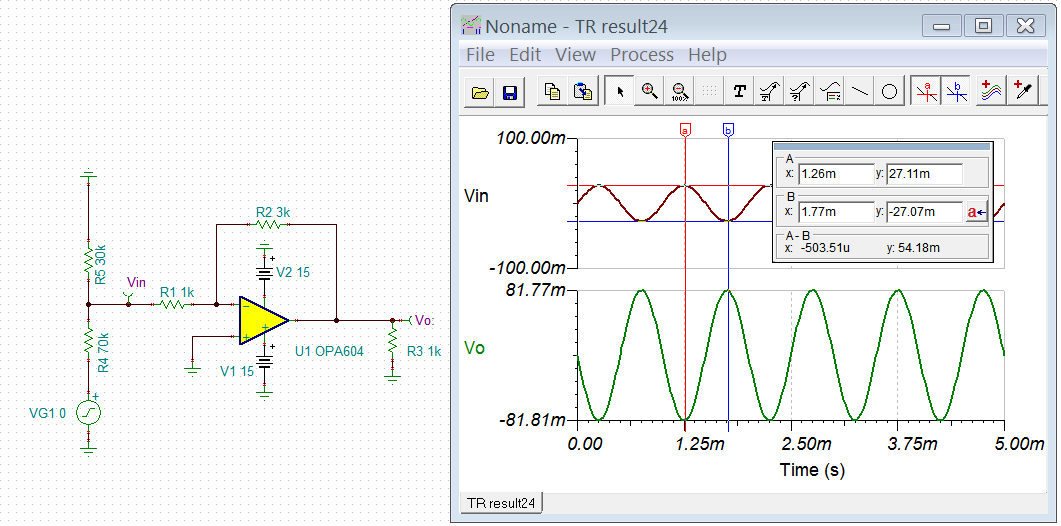
    If you are talking about the simulation, please see the image below. 

    If you are referring to your audio setup, I would recommend to check your output with DMM or scope, where Vout = - (R2/R1)*Vin.  Please verify it with DC input voltage. 

    Best,

    Raymond

  • Jason,

    First, your circuit is an inverting configuration (G=-1) and not a follower (G=+1).

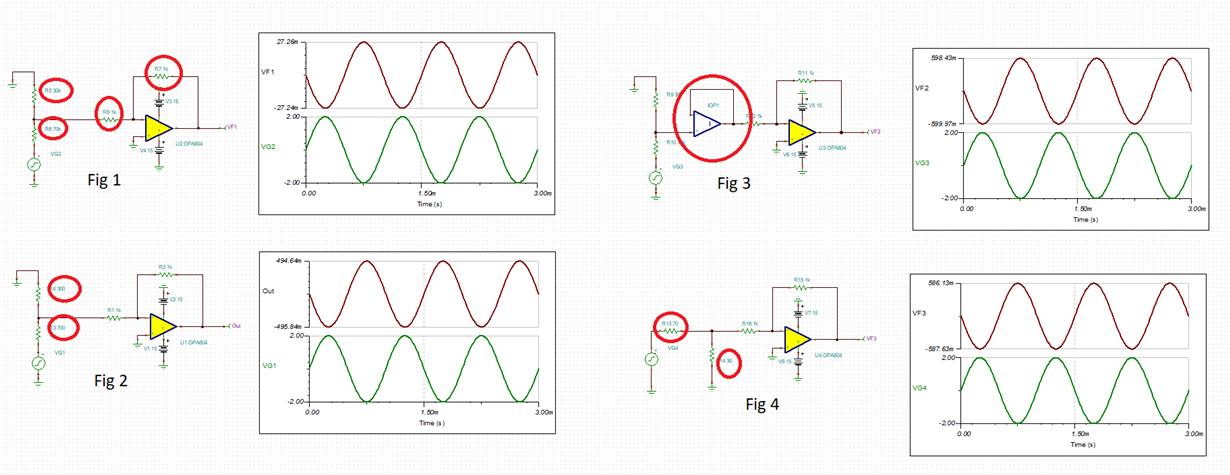
    You do not specify details of what is "not working" but I believe your problem is related to drivimg the op amp in an inverting configuration with high source resistance (30k||70k).  In Fig 1 below the input signal gets not only attanuated but also distorted because of large input current flowing into 1k input resistor vis-a-vis 30k||70k input source resistors.  Lower the value of input resistors in Fig 2 increases the input signal and decreases distortion BUT it would take a buffering of the input signal shown in Fig 3 to eliminate the distortion. Also, terminating the input signal with low value resistors (30ohm||70ohm) eliminates most of the distortion - see Fig 4.

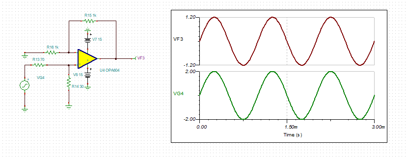
    However, it would require placing the op amp in a non-inverting configuration, by driving the non-inverting input, to eliminate the distortion caused by current in 1k input resistor - see below.

  • Jason,

    Some quick questions: Is the U2 op amp being used to drive the headphones directly, or is there another amplifier between U2 and the headphones?

    Also, you mention in the first sentence that U2 is configured as a simple voltage follower. That usually implies a non-inverting gain of +1 V/V, but in your case I think you intend that to mean a gain of -1 V/V as in the schematic you show. Then, in the last line you mention non-inverting gain of 3 V/V. Please clarify the configuration you are using.

    Regards, Thomas

    Precision Amplifiers Applications Engineering

  • I said the op amp is ”not working”, just like even the input signal is not connected ,  the output is very noisy and loudly. I will try the methods you mentioned, thanks a lot.

  • Hello, I am not asking about simulation, and I had done the simulation and there was no issue during the simulation, all the problems I mentioned are during the implementation.

  • Hello, the opamp isn't being used to drive the headphone directly, and it's a preamp with volume control, connected to a headphone amp with 3v/v to drive the headphone, which is the non inverting amplifier I mentioned before. The non inverting headphone amp doesn't have any issue with using the opamps I mentioned. But when I use those opamps for the preamp circuit, only tl072 and opa2111kp working fine, others op amps make the circuit totally unusable.

    I have tested the circuit multiple times, with the headphone amp I mentioned or just stand alone.

  • Update: I have done a test, those opamps with the issue, when the input is not connected there are 0.2 ~ 0.5 V output voltage(depends on which op amp), but with tl072 and opa2111kp(working good in my circuit), the output voltage are 0V when no input signal.  

  • Jason,

    What does it mean the input is not connected?  You CANNOT float the input or your output may end up anywhere between the rails. In order for the circuit to work properly, the input must be referenced to the system ground. If you have futher questions, please show the actual schematic of your circuit under test.

  • Hello, yes it means connected to the GND, the actual schematic is the image I uploaded. I think the problem is the DC offset too high, according to the datasheet, the offset voltage should be within +- 1 to 5 mv, but the offset voltage in my circuit is 0.2~0.5V. 

  • DC offset is tested in production so unless the part is damaged (check another unit) or oscillates (check the output for stability with a scope), it must be within the max limit.

    If the part does not osciallate or is damaged, please confirm the value of all resistors. Also, please confirm whether your actual circuit is shown in Fig 1 or Fig 2 below and what is the measured voltage at Vin?