This thread has been locked.

If you have a related question, please click the "Ask a related question" button in the top right corner. The newly created question will be automatically linked to this question.

OPA1652: Design balanced audio signal Splitter circuit by using OPA1652

Part Number: OPA1652
Other Parts Discussed in Thread: TINA-TI, OPA1637

Hello. 

I am designing a DAC for my application.

I am using AK4458VN DAC and a design a filter with OPA1652.

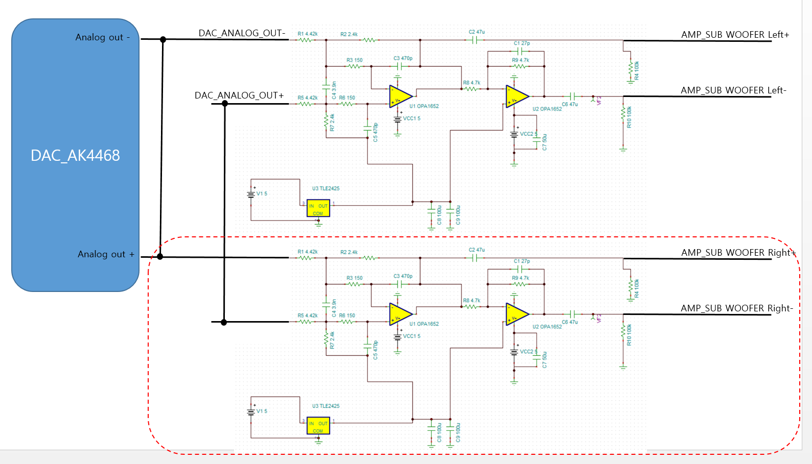
I am confusing how to design a splitter which can distribute 1 input to 2 output for subwoofer.

This figure illustrate a filter which is drive single channel output.

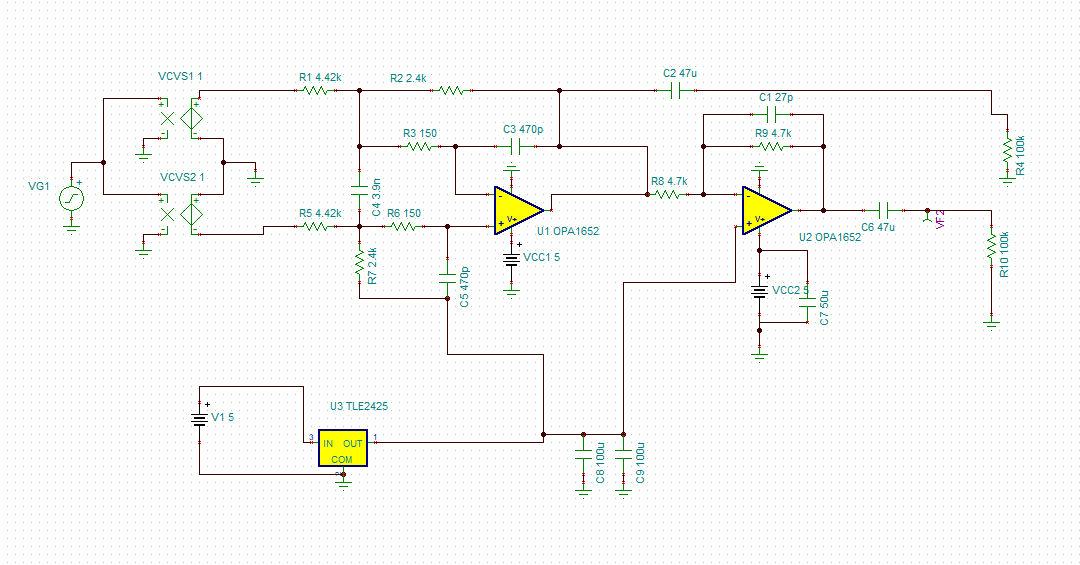
VCVS1, VCVS2 are balanced dac output and very right side is filtered output.

I would like to expand 2 filtered output with single input.(It is splitter right?)

Could you please give me a advice?

I added TINA-TI simulation file.7870.OPA1652_preamp_filter_01.TSC

  • Hi Jung,

    I would like to support your project.
    While, could you please provide your system block diagram with respect to this DAC output?
    It is very helpful to identify the right solution for you project.

    Thank you and Best regards,
    Iwata Etsuji

  • Hi Iwata Etsuji.

    Thank you for reply.

    Please take a look at below picture.

    I just wonder can I use that schematic to expand audio signal which is to class d amplifier input?

    (connect DAC anlog output signal parallel?)

    if it is not, how can I splitter signal DAC output signal for dual output?

    Thank you!

  • Hi Jung,

    I'm sorry for keep waiting you.

    Considering with AK4468/58 data sheet, I believe your schematic should work well as the split signal circuit.

    While, I would like to also propose alternative solution.
    As you can see the attached simulation file, you can also consider the post filter and output circuit for AK4458 with the full-diffrential opamps(FDA) due to its good THD performance of even order, especially we have launched the new FDA "OPA1637"dedicated to audio application.

    Audio-FDA-LPF03.TSC

    In the attached simulation file, I have designed the LPF with respect to Bessel filter coefficient.
    Please note that the TINA model for OPA1637 will be available later on TI.com. Sorry for inconvinience.

    Best regards,
    Iwata Etsuji

  • Hi Iwata, Thank you for great solution.

    That is exactly what I want! :)

    I have a question that is...

    what is purpose of two resistors(R4, R5) of 0 Ohm?

    Is it really necessary? Can I remove that resistors and connect route directly?

    I try to find that sample IC OPA1637 but it is not released yet. Can I buy that sample until this month?

    And I need EAGLE CAD LIBRARY OPA1637. Could you please release that one?

    PS: I think OUTP, OUTN should be swapped. :) 

    Really Thank you

  • Hi Jung,

    Sorry for your inconvenience.

    Now, as OPA1637 is in active status, its TINA spice model and its package CAD symbol  are available in the OPA1637 product folder.
    And its samples are also available in TI samples now.

    While, R4 and R5 (and also R6/11/13/15 ) resistors in my simulation file represents the footprints which sometimes help to improve the phase margin (i.e. dump the overshoot/ripple for some fast transient signal) if there are some cap load on the actual PCB/application.
    If any capacitive load were on your system could be well-controlled, those resistors might be not needed.

    Thank you and Best regards,
    Iwata Etsuji