Hi team,
Can you comment on my customers inquiry?
I can't get the integrated boost regulator of LM48511 to regulate at the fixed switching frequency of 1MHz (according to the data sheet). In continuous mode I see a maximum of 740kHz. Is this considered normal scattering or did I build-in an error?
In discontinuous mode the frequency is between 135kHz and 740kHz depending on the load.
My requirements:
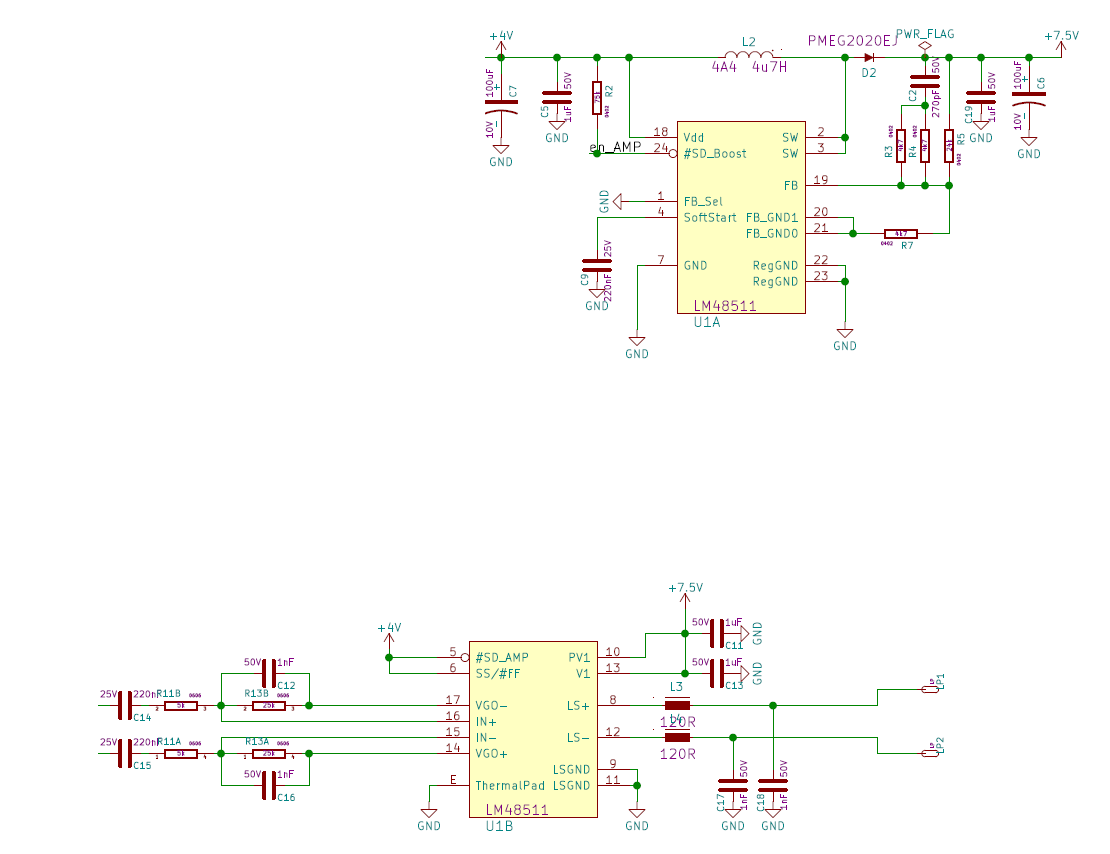
Vin = 4.1V
Cin =100uF
Feedback voltage dividers are 24k and 4k7 Ohm (-> Vout approx. 7.5V)
Cout = 100uF
Compensation network = 270pF + 2k4 Ohm (or 270pF + 3k6 Ohm in another attempt)
L = 4u7 H
My real problem is that in discontinuous mode (especially when idle) I still see too much EMI on the power supply line from the device (conducted EMI with 135kHz, 270kHz and 408kHz). I have to stay below 150kHz and the first harmonics are still higher. I have traced these back to the switching regulator. Therefore I would like to check the correct function of the switching regulator part first.
Thank you,
Franz