This thread has been locked.

If you have a related question, please click the "Ask a related question" button in the top right corner. The newly created question will be automatically linked to this question.

OPA1642: Offset drift parameter

Part Number: OPA1642
Other Parts Discussed in Thread: OPA1652, OPA1662, OPA2141, NE5532, OPA1678, OPA1679, OPA1688

Hello,

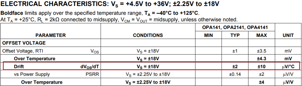
I was looking for information about offset voltage temperature dependence - opa1642 spice model does not include this. Using the cross reference tool I found this:

Is it possible? For JFET-Input? There is no information in the datasheet. Some other opamps give similar search results. Some pretty good bipolar opamps (for example opa1662) have 2-8 uV/C. Same with opa1652. No information or simulation for the good old 5532/4 and many others. What real values can I expect in practice? 

Thank you

  • Hi ,

    OPA1642 shares mostly the same Si die as OPA2141, which a typical Vos drift is specified at 2uV/C,  see the image below. 

    Best,

    Raymond

  • Wow, thanks a lot for the answer. That's basically what I wanted to know. So I can safely assume, that in case of OPA164X voltage drift will not exceed +/-10uV/C and taking into account the improvement of other parameters, it can be even a slightly better. But before I click 'resolved', it would be nice to find out what strategy to use for finding the missing parameters. For example, I can't find anywhere informations about the drift of good old NE5532/4. Where can I find information about similar structures to estimate how it will behave?

  • Hi V666,

    The NE5532 is an old part, and is intended for audio performance, not precision dc performance. Usually the dc specs of such op amps are not precision and not required for audio applications. We are unable to find  uV/°C spec that you are asking for. 

    What application the part is used for. Can we find a replacement for you? Please let us know. 

    Best,

    Raymond

  • It is quite funny that some audio applications require some precision for DC too :) 

    I'm designing a peak/rms compressor (which can also work as a limiter) and the sidechain block must include a logarithmic amplifier and a full-wave precision rectifier in front of it. I want to make the log-amp from scratch - a typical layout with two transistors, two op-amps and ptc temperature compensation (I don't want a ready-made integrated chip because I have my own concept of the detector circuit and the attack/release times control). Generally nothing special, but the logarithmic circuit is sensitive not only for the thermal dependence of transistor parameters, but also for offset of the opamps. Those in the rectifier too, because the offset at the input changes the operating point quite strongly. I've simulated the system on ideal models, ne5532 and OPA1642 but I think that opa1652 will work better (smaller and more predictable drift). I think it's also worth considering using OPA1662 in the rectifier, I need to find out which one works faster.

    I have a dilemma with op-amps simply buffering DC reference/compensation voltages. I don't require super-fast, absurdly low thd, audiophile-accepted sound but they should be chips:
    - operating reliably on +/-18V power supply, preferably +/-20V
    -relatively low noise (10nV/Hz^0.5 for 1kHz is absolute maximum, closer to 5 preferably). Low noise for low frequencies very desirable.
    -with temperature-stable DC parameters.
    -Stable as buffer
    -working with RL=2K or less (600 ohms preferably) at +/-18V supply voltage
    -with the highest possible input voltage range. The 3V margin from the power supply rails is an absolute maximum. 2V or less would be best.
    -Low output resistance for wide frequency spectrum preferably.
    -Low power consumption also(2mA or less)
    -not too expensive and easily accessible.

    I thought 5532 would be an overkill, but the lack of information about drifting and the lack of simulation of this parameter in the spice model and the fact that the recommended voltage range is only +/-15V (???) causes that I am considering a newer replacement, especially because this better workhorse will probably also be used in other projects. I'm open to suggestions about this and I will be grateful for your advice.

  • Hi V,

    Thank you for laying out all the requirements, it helps me narrow down our wide variety to a select few. I have a few options for you, take a look below:

    Option 1: OPA1678 / OPA1679. The OPA1678 is a dual-channel and the OPA1679 is a quad-channel operational amplifier intended for cost optimized audio applications.

    • It operates on +/-18V supplies and has a wide input common mode voltage range, 0.5V from the negative rail and 2V from the positive rail.
    • The device features low noise (4.5nV/rtHz), low offset (2mV maximum), and low drift (2uV/C typical). We do not specify a tested maximum limit on the drift spec, but it’s important to note that our “typical” specs will cover +/- 1 sigma on a Gaussian distribution. This means that 68% of the device population will be less than the typical value. So in this case, 68% of the devices would have less than 2uV/C of input offset voltage drift.
    • The OPA1678/1679 is also stable as a buffer with gain = 1V/ and with RL = 600 ohm. You can see the THD+N performance under these parameters on page 8 of the datasheet.
    • This device also has low and flat output impedance across frequency, this is shown in Figure 29 of the datasheet and below
    • OPA1678 consumes a maximum of only 2.5mA per channel of power.

    To view pricing and sample the OPA1678, click on this link: https://www.ti.com/product/OPA1678#order-quality

    Option 2: OPA1688 is a dual-channel audio amplifier.

    • It operates on +/-18V supplies and has a wide input common mode voltage range with extends 0.1V beyond the negative rail and 2V from the positive rail.
    • Voltage noise at 1kHz is 8nV/rtHz.
    • The maximum input offset voltage is 1.5mV and the maximum drift is 2uV/C.
    • The OPA1688 is unity gain stable and satisfies your 600ohm RL conditions.
    • The open loop output impedance is slightly complex (pictured below), so care will need to be taken in your design.
    • Power consumption is 1.8mA maximum.

    To view pricing and sample the OPA1688, slick on this link: https://www.ti.com/product/OPA1688#order-quality

  • Hi Tamara,

    Thanks a lot for the answer.Both options make sense and should work fine. Of course, first I will test both variants in the simulation and then I will decide which chips should be dual and which quad. I also need to check how important is the drift sign itself for this particular application.