This thread has been locked.

If you have a related question, please click the "Ask a related question" button in the top right corner. The newly created question will be automatically linked to this question.

CCS/AICPUREPATH_STUDIO: Problems creating process flow to work with CC3220SF-LAUNCHXL and CC3200AUDBOOST

Part Number: AICPUREPATH_STUDIO

Tool/software: Code Composer Studio

I am developing an audio application initially using a CC3220SF-LAUNCHXL launchpad with a CC3200AUDBOOST booster pack. I need VOX functionality so have created a process flow to provide this in PurePath Studio.

I have created a process flow and tested it successfully on a TLV320AIC3254EVM-K development board.

I have then taken the contents of the header file created by PurePath Studio and tried to incorporate it into the i2secho example included in the CC3220SF SDK as per the instructions in https://www.ti.com/lit/an/slaa605a/slaa605a.pdf , however I get no audio except for a few clicks at startup.

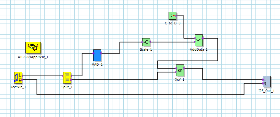
This is the process flow I have created. The only part I actually need for production is the path from left input to left i2s output, the other elements are for test purposes only.

Using the TLV320AIC3254EVM-K I get audio constantly on the right ear and audio when the VAD triggers on the left ear. My scope shows i2s data coming out of the EVM-K when the VAD triggers. 

In the i2secho example I have replaced the AudioCodec_config method with the call to AIC_Init(0x30) and have changed the commands to control the i2c from

GPIO_I2C_Write(address,data[i].reg_off,data[i].reg_val) used in the PurePath example to

AudioCodec_regWrite(data[i].reg_off,data[i].reg_val) as used by the i2secho example.

I get no audio and no data in the i2s read callback

Thanks in Advance

Chris

  • I have been experimenting with the proce - still struggling unfortunately. This is the process flow i have now with thss flow and trying to combine the codec configuration from the i2secho sample with the code generated by PurePath Studio.

    I am getting some audio, but at a very low level.

    This is the process flow I have now:

  • Hi Chris,

    If you have the flow working with the EVM-K board and not working when the settings are exported to another board, then the issue could be related to the difference in clocking.

    Please note that the device on the EVM-K board takes the MCLK from the TAS1020B USB Controller and derives all the internal clocks using a PLL and dividers. The MCLK is likely different on this SimpleLink board. If they are different then the PLL configuration registers - i.e. P, R, J, D , NADC, MADC, NDAC, MDAC - would have to be changed to suit the Master Clock Frequency.

    Would you be able to check and confirm the input clock to the device on the SimpleLink board? Please also list down the PLL configuration registers for the EVM-K. I can suggest suitable replacements.

    Best Regards.

  • Hi Diljith

    Thank you for your response.

    I am running 16 bit audio with 16 kHz sample rate. The settings in the i2secho example are listed as 

    MCLK = BCLK

    Fs = 16kHz, BCLK = input to PLL, BCLK = 512kHz

    The example does not include any other settings for the PLL registers when running at 16 KHz sample rate, but does set them for higher sample rates - I assume that for 16 KHz it uses defaults, but I have not been able to confirm this?

    The settings created by PurePath Studio are

    //          # reg[  0][  5] = 0x91  ; P=1, R=1, J=24
    //          # reg[  0][  6] = 0x18  ; P=1, R=1, J=24
    //          # reg[  0][  7] = 0x00  ; D=0000 (MSB)
    //          # reg[  0][  8] = 0x00  ; D=0000 (LSB)
    //          # reg[  0][  4] = 0x03  ; PLL_clkin = MCLK, codec_clkin = PLL_CLK, PLL on
    //          # reg[  0][ 12] = 0x88  ; MDAC = 8, divider powered on
    //          # reg[  0][ 13] = 0x01  ; DOSR = 384 (MSB)
    //          # reg[  0][ 14] = 0x80  ; DOSR = 384 (LSB)
    //          # reg[  0][ 18] = 0x02  ; NADC = 2, divider powered off
    //          # reg[  0][ 19] = 0x98  ; MADC = 24, divider powered on
    //          # reg[  0][ 20] = 0x80  ; AOSR = 128
    //          # reg[  0][ 11] = 0x82  ; NDAC = 2, divider powered on
    

    Best Regards

    Chris

  • Hi Diljith

    Just to add a bit more information - in the I2S initialisation parameters for the CC3220 the MCLK Divider is set to 40:

    /*!
     *  @brief  Function to initialize the I2S_Params struct to its defaults
     *
     *  @param  [out]   params  An pointer to I2S_Params structure for
     *                          initialization
     *
     *  Defaults values are:
     *  @code
     *  params.samplingFrequency    = 16000;
     *  params.memorySlotLength     = I2S_MEMORY_LENGTH_16BITS;
     *  params.moduleRole           = I2S_MASTER;
     *  params.trueI2sFormat        = (bool)true;
     *  params.invertWS             = (bool)true;
     *  params.isMSBFirst           = (bool)true;
     *  params.isDMAUnused          = (bool)false;
     *  params.samplingEdge         = I2S_SAMPLING_EDGE_RISING;
     *  params.beforeWordPadding    = 0;
     *  params.bitsPerWord          = 16;
     *  params.afterWordPadding     = 0;
     *  params.fixedBufferLength    = 1;
     *  params.SD0Use               = I2S_SD0_OUTPUT;
     *  params.SD1Use               = I2S_SD1_INPUT;
     *  params.SD0Channels          = I2S_CHANNELS_STEREO;
     *  params.SD1Channels          = I2S_CHANNELS_STEREO;
     *  params.phaseType            = I2S_PHASE_TYPE_DUAL;
     *  params.startUpDelay         = 0;
     *  params.MCLKDivider          = 40;
     *  params.readCallback         = NULL;
     *  params.writeCallback        = NULL;
     *  params.errorCallback        = NULL;
     *  params.custom               = NULL;
     *  @endcode
     *
     *  @param  params  Parameter structure to initialize
     */

    Best Regards

    Chris

  • Thanks for the additional inputs. I shall work out the PLL clock tree for this configuration and get back to you in a day.

    Best Regards.

  • Hi Chris,

    Please use the attached clock-tree for your process flow.

    The Application Reference Guide (www.ti.com/lit/slaa408a) contains information regarding the clock tree registers

    Select BCLK as PLL input and program the 11 registers shown in green for clock tree configuration.

    Let me know if you face any hurdles.

    Best Regards.

  • Hi Diljith

    Thanks for putting this together for me, I will incorporate these values into my code and test and report back.

    Is there a document that works through the process of creating the clock tree please. for my future reference? I can understand the structure from the clock tree in the application reference guide, but now how to calculate the respective values

    I tried to use the PLL calculator in the AIC3254 CS application, but I ended up with very different settings to those you list, and could not get them to work

    Many Thanks

    Chris

  • The ARG has all the info. for configuring the clock tree. I believe all the constraints are documented in it. 

    The auto-calculate tools are helpful but for simple integer ratios it is easier to work it by hand.

    I have used an excel calculator for this. The Dividers tab of the GUI is also pretty handy for verifying simple integer dividers.

  • Hi Diljith

    Thanks for the extra information. I will look again at the ARG - obvioulsy I missed something previously.

    The clock tree settings you provided worked  a treat, thank you, so I am now all up and running.

    Many Thanks

    Chris