This thread has been locked.

If you have a related question, please click the "Ask a related question" button in the top right corner. The newly created question will be automatically linked to this question.

TLV320AIC3256: miniDSP's not running?

Part Number: TLV320AIC3256

Hi,

We're trying to get the AIC3256 running in a new design and have an issue where it seems like the miniDSP's are not running.

Reading/writing over I2C to load the codec seems to be working fine.

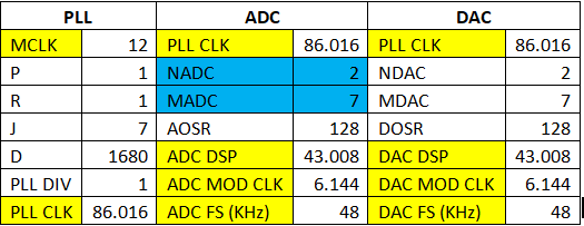
VSYS, IOVDD = 3.01v, DVDD, AVDD, HPVDD and DVDD_CP are all 1.86v, MCLK = 12MHz.

Here's the PPS generated control registers (Works as expected on the EVM-U):

{ 0,0x00},
{ 1,0x01},// # reg[ 0][ 1] = 0x01 ; Initialize the device through software reset
{254,0x0A},
{ 0,0x01},
{124,0x06},// # reg[ 1][124] = 0x06 ; Charge Pump 1x Current, 333kHz clock (8MHz/(6*4))
{ 1,0x0A},// # reg[ 1][ 1] = 0x0a ; Disable weak AVDD to DVDD connection, use OSC for CP
{ 2,0x00},// # reg[ 1][ 2] = 0x00 ; Enable Master Analog Power Control
{ 71,0x32},// # reg[ 1][ 71] = 0x32 ; Set the input power-up time to 3.1ms
{123,0x05},// # reg[ 1][123] = 0x05 ; Force REF charging time to 40ms
{255,0x00},
{255,0x01},
{ 0,0x00},
{ 60,0x00},// # reg[ 0][ 60] = 0x00 ; Use miniDSP_D for signal processing
{ 61,0x00},// # reg[ 0][ 61] = 0x00 ; Use miniDSP_A for signal processing
{ 17,0x08},// # reg[ 0][ 17] = 0x08 ; 8x Interpolation
{ 23,0x04},// # reg[ 0][ 23] = 0x04 ; 4x Decimation
{ 15,0x03},
{ 16,0x88},
{ 21,0x03},
{ 22,0x88},
{ 0,0x08},
{ 1,0x04},// # reg[ 8][ 1] = 0x04 ; adaptive mode for ADC
{ 0,0x2C},
{ 1,0x04},// # reg[ 44][ 1] = 0x04 ; adaptive mode for DAC
{ 0,0x00},
{ 5,0x91},// # reg[ 0][ 5] = 0x91 ; P=1, R=1, J=8
{ 6,0x08},// # reg[ 0][ 6] = 0x08 ; P=1, R=1, J=8
{ 7,0x00},// # reg[ 0][ 7] = 0x00 ; D=0000 (MSB)
{ 8,0x00},// # reg[ 0][ 8] = 0x00 ; D=0000 (LSB)
{ 4,0x03},// # reg[ 0][ 4] = 0x03 ; PLL_clkin = MCLK, codec_clkin = PLL_CLK, PLL on
{254,0x0a},
{ 12,0x87},// # reg[ 0][ 12] = 0x88 ; MDAC = 7, divider powered on
{ 13,0x00},// # reg[ 0][ 13] = 0x00 ; DOSR = 128 (MSB)
{ 14,0x80},// # reg[ 0][ 14] = 0x80 ; DOSR = 128 (LSB)
{ 18,0x02},// # reg[ 0][ 18] = 0x02 ; NADC = 2, divider powered off
{ 19,0x87},// # reg[ 0][ 19] = 0x88 ; MADC = 7, divider powered on
{ 20,0x80},// # reg[ 0][ 20] = 0x80 ; AOSR = 128
{ 11,0x82},// # reg[ 0][ 11] = 0x82 ; NDAC = 2, divider powered on
{ 0,0x01},
{ 51,0x40},// # reg[ 1][ 51] = 0x40 ; Mic Bias enabled, Source = Avdd, 1.25V
{ 52,0x40},// # reg[ 1][ 52] = 0x40 ; Route IN1L to LEFT_P with 10K input impedance
{ 54,0x40},// # reg[ 1][ 54] = 0x40 ; Route CM1L to LEFT_M with 10K input impedance
{ 55,0x40},// # reg[ 1][ 55] = 0x40 ; Route IN1R to RIGHT_P with 10K input impedance
{ 57,0x40},// # reg[ 1][ 57] = 0x40 ; Route CM1R to RIGHT_M with 10K input impedance
{ 59,0x00},// # reg[ 1][ 59] = 0x00 ; Enable MicPGA_L Gain Control, 0dB
{ 60,0x00},// # reg[ 1][ 60] = 0x00 ; Enable MicPGA_R Gain Control, 0dB
{ 0,0x00},
{ 81,0xC0},// # reg[ 0][ 81] = 0xc0 ; Power up LADC/RADC
{ 82,0x00},// # reg[ 0][ 82] = 0x00 ; Unmute LADC/RADC
{ 0,0x01},
{ 12,0x08},// # reg[ 1][ 12] = 0x08 ; Route LDAC to HPL
{ 13,0x08},// # reg[ 1][ 13] = 0x08 ; Route RDAC to HPR
{ 14,0x08},// # reg[ 1][ 14] = 0x08 ; Route LDAC to LOL
{ 15,0x08},// # reg[ 1][ 15] = 0x08 ; Route LDAC to LOR
{ 0,0x00},
{ 63,0xD4},// # reg[ 0][ 63] = 0xd4 ; Power up LDAC/RDAC w/ soft stepping
{ 0,0x01},
{125,0x12},// # reg[ 1][125] = 0x12 ; GCHP Mode, Offset corr Enabled on present routing
{ 16,0x00},// # reg[ 1][ 16] = 0x00 ; Unmute HPL driver, 0dB Gain
{ 17,0x00},// # reg[ 1][ 17] = 0x00 ; Unmute HPR driver, 0dB Gain
{ 18,0x00},// # reg[ 1][ 18] = 0x00 ; Unmute LOL driver, 0dB Gain
{ 19,0x00},// # reg[ 1][ 19] = 0x00 ; Unmute LOR driver, 0dB Gain
{ 9,0x3C},// # reg[ 1][ 9] = 0x3c ; Power up HPL/HPR and LOL/LOR drivers
{ 0,0x00},
{ 64,0x00},// # reg[ 0][ 64] = 0x00 ; Unmute LDAC/RDAC
{ 26,0x82},// # reg[ 0][ 26] = 0x82 ; CDIV_CLK = MCLK, CLKOUT M DIVIDER = 2
{ 52,0x10} // # reg[ 0][ 52] = 0x10 ; MPF5 = CLK_OUT

I've added in outputting MCLK/2 on MPF5, this works as expected. 

The miniDSP code that's loaded is just a tone generator to the HP outputs.  I've checked multiple times and it is set to run at load, frequency 1k, amplitude 0.9..

I've tried adding a delay after forcing reference, this didn't make any difference.

I've also tried using the power initialization for the non-EVM-U board in PPS, again this didn't make any difference.

All voltages to the codec look good.  Any suggestions on what to look for?

Thanks in advance.

  • Hi Lance,

    I hope you have tested the flow on the EVM board and made sure it is working fine. If so then the issue could be with regard to the clocking.

    What is the clocking scheme on your board? Is it MCLK or BCLK? The clock tree would have to be derived accordingly.

    Best Regards.

  • Hi,

    Thanks for your reply.

    Yes, the flow does work correctly on the EVM-U.  

    I went back and changed the clock tree to match what is in Table 2-23 for a 12Mhz MCLK and 48k Fs.  Still nothing from the headphones.  Here's the clock setup as it stand now:

    { 0,0x00},
    { 5,0x91},// # reg[ 0][ 5] = 0x91 ; P=1, R=1, J=7
    { 6,0x07},// # reg[ 0][ 6] = 0x07 ; P=1, R=1, J=7
    { 7,0x06},// # reg[ 0][ 7] = 0x06 ; D=1680 (MSB)
    { 8,0x90},// # reg[ 0][ 8] = 0x90 ; D=1680 (LSB)
    { 4,0x03},// # reg[ 0][ 4] = 0x03 ; PLL_clkin = MCLK, codec_clkin = PLL_CLK, PLL on
    {254,0x0a},
    { 11,0x82},// # reg[ 0][ 11] = 0x82 ; NDAC = 2, divider powered on
    { 12,0x87},// # reg[ 0][ 12] = 0x88 ; MDAC = 7, divider powered on
    { 13,0x00},// # reg[ 0][ 13] = 0x00 ; DOSR = 128 (MSB)
    { 14,0x80},// # reg[ 0][ 14] = 0x80 ; DOSR = 128 (LSB)
    { 18,0x87},// # reg[ 0][ 18] = 0x02 ; NADC = 7, divider powered on
    { 19,0x82},// # reg[ 0][ 19] = 0x88 ; MADC = 2, divider powered on
    { 20,0x80},// # reg[ 0][ 20] = 0x80 ; AOSR = 128
    {254,0x0a},

  • Hi Lance,

    I see that even through you are not using the ADC you are powering on the ADC. In that case I suggest you use the slightly modified version of the clock-tree as shown below. The blue cells have changed to ensure that the miniDSPs attached to the DACs and ADCs run at the same rate.

    A few other things to check while debugging -

    • In order to check if the DACs and ADCs are running, you can read the flag registers (Page 0, Registers 36-38).
    • Page 0, Register 26 has options to route DAC clocks to the MFP5 and that can be used to check if the clocking is working properly.

    I hope these pave the way to turning things around. Let me know if you are still stuck.

    Best Regards.

  • Hi Diljith,

    I've tried what you suggested with swapping NADC and MADC, and am also outputting DAC_MOD_CLK on MPF5.  It looks like a good 6.144Mhz, as expected.

    The flag register reads are:

    [0][36] = 0x44, Left and Right ADC powered up, gain applied != gain programmed, not saturated.

    [0][37] = 0xee, RDAC, LDAC, HPR, HPL, LOR, LOL all powered

    [0][38] = 0x00, gain applied != gain programmed

    Still no output.

    We really appreciate your help with this.

  • Hi Lance,

    1. Did you by any chance create the header file with the tone generator turned off?

    2. Can you confirm that the miniDSP program and coefficient registers are getting programmed for the  {255,0x00} and {255,0x01} cases?

    Best Regards.

  • Hi,

    The tone generator coefficients are located at [44][28-31] for the status register according to PPS.  Looking at that in the generated file, the value is 0x00010000 = RUN.  When I read this location from the codec, I am reading 0x00010000.

    I've also tried reading the DAC instructions starting at [152][8] and the values read do match what's in the generated file.

    So it does look like it's set to run, and it is getting programmed during the load process.

  • On a side note, we have been able to confirm also that when we route IN1L+R to the HP outputs this does work, it just seems that no matter what we do, we just can't get any flow to work with the miniDSPs.  We've used the AIC3262 and AIC3254 both in the past, and never encountered an issue like this.

  • Could you check the BCLK and WCLK inputs to the device? Are they the right frequency and do they look good?

    Best Regards.

  • Hi Diljith,

    In our setup, we wanted to have to codec generating the WCLK and BCLK for our I2S interface.  Since we haven't been concerned yet with testing that interface on our board, we haven't had them enabled.  As soon as I enabled generating of WCLK and BCLK, everything is working.

    Thank you so much for your help and guidance.  So very much appreciated.