This thread has been locked.

If you have a related question, please click the "Ask a related question" button in the top right corner. The newly created question will be automatically linked to this question.

ADC5140EVM-PDK:

Part Number: ADC5140EVM-PDK

hi,sir  

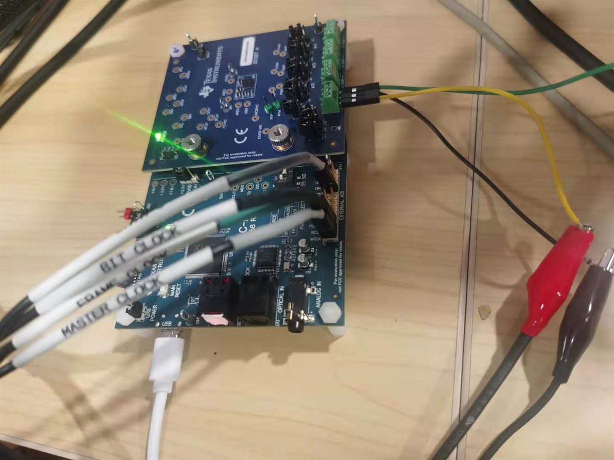
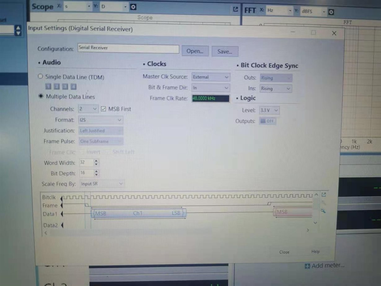
  For the above test path, the IIS output of ADC5140 is master and synchronous clock data is sent to AP.

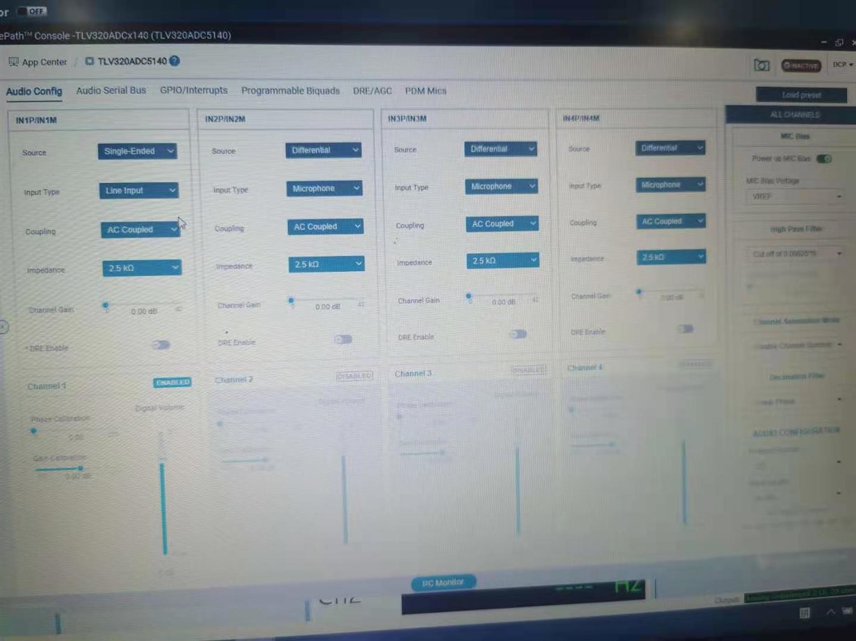
 but  found the board IIS pin ,have no waveform,i think ,there is ADC5140 config wrong??

please help me check??

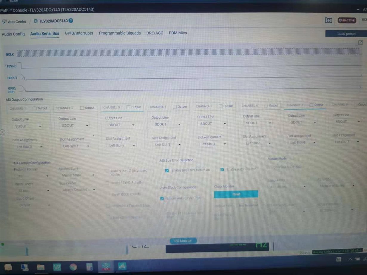
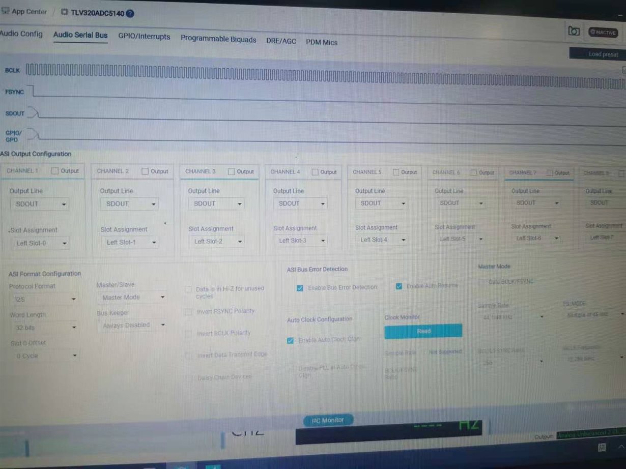
clock moniter frame clk not supported,

  • Hello,

    It's a little hard to see the screen images but it doesn't look like you have any output channels enabled to Slot-0/Slot-1 for the 2-channel out I2S configuration it looks like you're trying to achieve.

    Also, it looks like the audio signals are possible connected in the wrong polarity from the AP.  The GND connections are on the outside of the board as the labels on the board show.

  • Let me summarize:

    there is two test scene:

    1. ap with master,adc5140 ASI with slave,so the hardware wiring GND is inside the board? 

    2.ap with slave,adc5140 ASI with master,so the hardware wiring GND is outside the board? 

    3.In both cases, the S0 switch is dialed to OFF? 

    4. we test the board test pin with codec MCLK,FRAMECLK...the wav is wrong, And the signal quality was poor

  • hi sir,

       please check my attachment

    the test scene :

    test step:

    1.switch S0 with ON

    2.ap with slave,ADC5140 ASI with master, i do the  hardware wiring GND is outside the board,

    3. and ap digtal serial with TDM mode,with word len 32bit ,and i config one ended single channel,so ap with 2channel num.

    help me check  the config whether right ro not ?

  • clk mointer check the frame clk 48k,but why ap dect 192k??

  • Hello,

    1.)  The pins closest to the outside of the board on the "External ASI" header are the GND signals.

    2.)  Same answer as above.

    3.)  "External ASI" requires the S0 to be in the "OFF" position or you'll have a bus contention issue between the signals.

  • In the next thread:

    1.) Switch S0 with ON

    S0 should still be in the "OFF" position in order to use the AP with the EVM.

    2.ap with slave,ADC5140 ASI with master, i do the  hardware wiring GND is outside the board,

    Good, GND is on outside of the board.  You'll still need to make sure the AP is outputting the BCLK signal so the ADCx140 can use it to generate the FSYNC and DOUT outputs.

    3. and ap digtal serial with TDM mode,with word len 32bit ,and i config one ended single channel,so ap with 2channel num.

    These settings look correct other than that CH2 is not enabled on the main analog page even though it's being slotted to Slot-1.

  • hi sir,


    In the next thread:

    1.) Switch S0 with ON

    S0 should still be in the "OFF" position in order to use the AP with the EVM.

    2.ap with slave,ADC5140 ASI with master, i do the  hardware wiring GND is outside the board,

    Good, GND is on outside of the board.  You'll still need to make sure the AP is outputting the BCLK signal so the ADCx140 can use it to generate the FSYNC and DOUT outputs.

    3. and ap digtal serial with TDM mode,with word len 32bit ,and i config one ended single channel,so ap with 2channel num.

    These settings look correct other than that CH2 is not enabled on the main analog page even though it's being slotted to Slot-1.

    i test with you advise please check my attachmen

    but ap frame clk is also wrong

  • hi sir

       the PPC3 GUI read the bclk/frame  ratio with 64 div,but samle rate can not sync ok,i check my ap found

    mck/fclk=64 ,and show the frame clk rate 1.7khz

  • hi sir

       i test the codec pin MCLK BLCK FRAME CLK is ok,but there is no data with codec DOUT pin?why?

  • ap with master or slave, there is also no data with CODEC DOUT pin

  • ap with master or slave, the CODEC DOUT PIN no data,MCLK BCLK FRAMECLK is ok