


Other Parts Discussed in Thread: TPA3110D2
Hello Team,
This is Swapnil S.
We got following THD data on TPA3110D2 EVM board.
LC filter value:- L:-22uH & C:- 0.68uF
Input Waveform :- 1KHZ , Vrms :- 916 mVrms (near to 1Vrms )
Load :- Speaker 8ohm
Stereo Mode
Plimit setting :- 6.97V. Directly connect to GVDD.
Result:-
PVCC 10V DC , THD :- 11%
PVCC 12V DC, THD :- 5.6%
PVCC 13.5V DC, THD :- 3.8%
PVCC 16V DC, THD :- 1.8%
Observation:-
1. We are getting glitchy square wave before LC filter. As per below snap.
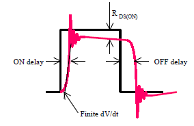
2. So, As per our study it happed due to "Dead time" concept of MOSFET which is used internally in IC.
3. Please share your valuable comments to reduce THD .
Regards,
Swapnil
