Hi team,
one question about PCM6240 Sampling. I see there only have one I2S output SOUT. when there have 4 mic input, what's the I2S output?
does it can support convert 4 channel input at the same time? what's the sequence?
thank you
This thread has been locked.
If you have a related question, please click the "Ask a related question" button in the top right corner. The newly created question will be automatically linked to this question.
Hi team,
one question about PCM6240 Sampling. I see there only have one I2S output SOUT. when there have 4 mic input, what's the I2S output?
does it can support convert 4 channel input at the same time? what's the sequence?
thank you
Hi Betty,
The device supports an extrapolation of the I2S protocol where 4 channels can be placed on a single data line, or alternatively if you want to use true I2S then one of the GPIO pins can be configured as a secondary SDOUT and you can assign the data to the left and right channels of each SDOUT pin.
Best,
Zak
Hi Betty,
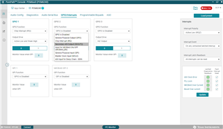
This is most easily demonstrated using the GUI. Any of the GPIOs can be set to act as a secondary data output as shown below:

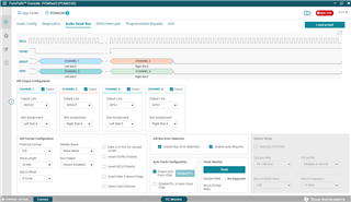
Once the SDOUT2 function is selected, the Output Drive should be set to active high and active low. From there, each of the channel outputs can be assigned to either SDOUT or GPIO. The slot assignments need to be chosen accordingly (left slot 0 and right slot 0 for each data pair for traditional I2S). Here is an example of this configuration:

Best,
Zak