This thread has been locked.

If you have a related question, please click the "Ask a related question" button in the top right corner. The newly created question will be automatically linked to this question.

TS3A227E: Problems in the design of TS3A227E

Part Number: TS3A227E

Hi Sir,

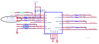
I have encountered several problems when designing with TS3A227 and ALC256 (Audio Codec), and the schematic diagram of TS3A227 is as follows:

My problems are as follows:

1) Did the DVT circuit can realized the control of the earphone function and the wire control function? Is there any problem with the line connection and need to be adjusted?

2) When the rear LINE IN or LINE OUT is inserted first, and then the front earphone is inserted, the front MIC can be recognized, but the MIC function does not work normally. we have found that TS3A227 has no signal sent to PORTB, and the other port functions are correctly identified and functioning normally. 

3) Insert the 4-segment earphone on the front panel, the MIC wind function of the front panel earphone is abnormal.The voltage of the AR1058/AR1060 resistance terminal is measured to be 0V, while the normal recognition is about 2.28V.

Can u help to check if there is any problem with the circuit design and give some suggestions? If the entire circuit design was needed, I can send it to you offline.

Thanks,

Best Regards

  • Hi Lumina,

    It would be very helpful if you could include the parts of the schematic of where the inputs to the TS3A227 are coming from. Connections look fine from a high level standpoint, but would need to see the exact inputs to give a better idea of what is going on.

    Thanks!
    Bryan

  • Hi Bryan,

    Sorry to reply so late. I have added the audio design schematic to the below, pls check it.

    DT03 CX20632 SCH.pdf

    Thanks,

    Kind Regards

  • Hi Lumina,

    Thanks for sending over the full schematic. Will take a closer look and let you know our suggestions.

    Thanks!

    Bryan

  • Hi Lumina,

    After taking a look through, here are my suggestions:

    1) Make sure to add decoupling capacitors to your VDD rails. This will help ensure stability of the device.

    2) The MICP signal should not be connected to both the Sleeve and Ring. This should be connected directly to the MIC signal.

    3) I would remove that 10K resistor you have going to GND. This could cause distortion for your circuit.

    4) The 0 Ohm resistors can cause some error on the RING and SLEEVE lines as these are pretty sensitive and need to be accurate.

    5) For the SENSE lines for the Sleeve and Ring, it is advised to tie them as close to the input pins as possible. Maybe it is done like that on the PCB already, but something to check.

    6) Check to make sure your audio jack inputs are going to the correct input on the TS3A227E. I cannot tell directly from your schematic, but would be good to double check the Sleep and Ring2 lines are being connected at the right place.

    Thanks!

    Bryan

  • Hi Lumina,

    Have not heard from you in a while so will close this thread. If you have any questions, please reach out and we will be happy to assist.

    Thank you,

    Regards,

    Sandesh

  • Hi Sandesh,

    Sorry to reply u so late.

    We have modified the schematic diagram according to your suggestion, but found a new problem after the board came back when testing. The problem description is as follows:

    1) When the rear is plugged into LINEOUT first, and then the front headphones CTIA and OMTP are switched, there will be a problem of audio distortion in playback (F/R: 2/5DUTs, 5/11Cycles).

    2) There is no problem when LILNEOUT is inserted in the rear and only CTIA or OMTP earphones are used in the front.


    We have tried to find the cause of the problem with the following test actions:

    Insert the rear earphone first and keep it still, repeatedly unplug and insert the front earphone, which can repeat the problem.

    TS3A227E is used to realize the headphone channel switching function. When the front headphone is unplugged, it is found that the register 0x0B, 4-pole standard still remains recognized, the internal control switch is still keep opening, and the unplugged headphone cannot be restored, resulting in audio distortion.

    Can u help to analyze the cause of this problem and give us some suggestion?

    Thanks,

    Best Regards

  • Hi Lumina,

    Do you have the latest schematic for this? If you have made those suggestions in my previous post, then the part should be setup correctly.

    Thanks,

    Bryan

  • Hi Bryan,

    We have update our schematic with your previous suggestion and encountered the problem that I have describe on my previous post. The latest schematic is as belows:

    DT03 AUDIO SCH_0527.pdf

    When the problem occurred yesterday, the following questions were found by grabbing the relevant register values:

    1)The rear LINE OUT plugs in a 3-segment earphone first, and after the front-plugged earphone is unplugged, the register value is still the register value of the front earphone. After the headset is unplugged, the readout should be the register of the three-segment headset.

    2) Theoretically, the front port should be reset after the device is unplugged to prepare for the identification of the next device plug-in, not after the device is unplugged, it still recognizes the register value of the plug-in device.

    We did a verification experiment yesterday. After the front earphone device is unplugged, EC resets the TS3A227E, and then switches the earphone, the audio will not be invalid. 

    The rear earphones are keep plugged in, and the device on the front port is plugged in or unplugged, does the TS3A227E need to be reset every time? For example, when the CTIA and OMTP headsets are switched.

    According to the register table on the TS3A227E datasheet, we found that it has the reset function. Please confirm that whether we can use it.

    Thanks,

    Best Regards

  • Hi Lumina,

    I will get back to you by 6/01. Will be out of the office until then.

    Thanks!

    Bryan

  • Hi Lumina,

    It looks to me that the latest schematic has all of the necessary changes needed for our switch to work as intended. I would still advise to remove that 10K ohm resistor to GND that is present though to reduce any further distortion.

    Our switch should work perfectly fine without needing to reset each time after taking out and inserting a new device as the detection scheme should automatically do this if connected properly. You can of course use that reset register to do this as well, but it should not be necessary.

    It looks to me there is something along the signal path to the input to the TS3A227E device that is not correct, but that is very difficult for me to evaluate from just the schematic. I would make sure the detection sequence is correct as your next debugging step as that is most likely where something is not working as intended (checking DET_TRIGGER and MIC_PRESENT signals at time of insertion).

    Thanks,

    Bryan

  • Hi Bryan,

    Thanks for your suggestion. 

    As for the schematic, I was wondering if it would be better to  connect the GND_SENSE pin to GND with a 0Ω resistor instead of the10KΩ resistor, rather than simply disconnect in floating state?

    Thanks,

    Kind Regards

  • Hi Lumina,

    That would be a much more reliable approach. Removing that 10K and replacing with a 0ohm as you stated would be good idea.

    Thanks!

    Bryan

  • Hi Bryan,

    Regarding the key press function of earphones, what conditions need to be met in order to support different earphones? Does it need to know all the different headset key press impedance table to make adaptations? Or just need to follow key press thresholds on the datasheet?

    Thanks,

    Best Regards

  • Hi Lumina,

    That is correct. Just need to follow the resistance thresholds as specified in the datasheet to distinguish between the different key presses.

    Thanks,

    Bryan

  • Hi Bryan,

    Now we encountered another serious problem, that is, when the device is turned off and then turned on again, the headset key have no function, and the volume is automatically adjusted to the minimum. The problem is shown in the video below.

    At this time, the front earphone with button function will have this problem, the volume is directly pulled to the minimum, or the button +/- has no function.

    In addition, the MICP pin (6 pin) of TS3A227E is connected to MICBIAS. Is there any voltage demand for this PIN for it? 2.2V, 2.7V or other voltage?

    Thanks,

    Best Regards

  • Hello Lumina,

    That could be caused by several different things and not exclusively related to the TS3A227E, so it would be very challenging to debug based off the schematic alone. For the button key presses, make sure the MICBIAS voltage is applied before enabling the key press detection:

    In regards to the MICP pin, the MICBIAS/MICP relationship is clarified in this section of the datasheet.

    Thanks,

    Bryan