This thread has been locked.

If you have a related question, please click the "Ask a related question" button in the top right corner. The newly created question will be automatically linked to this question.

TAS2560: PDM Interface not used and connected

Part Number: TAS2560
Other Parts Discussed in Thread: , TAS2562

Hi all,

when used in mode 3 (I²S Playback), is it possible to leave the pins PDMCLK and DOUT unconnected and floating?

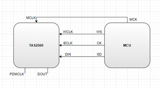
Our product is a docking station for tablets, which integrates a 5 W 4 Ohm full range speaker. We have been recommended the TAS2560 by the speaker supplier. We are planning to use the TAS2560 in mode 3 with I²S playback. Our MCU (STM32F103) provides one I²S, either master/slave, send/receive only. We would like to find good register settings for our speaker with the TAS2560EVM and not do any audio processing in the final product anymore. Does this sound like a reasonable plan?

Best regards

Jakob

  • Hi Jakob,

    First of all let me comment you could take a look at TAS2562. This is update from TAS2560 with higher internal boost range, useful in case you need higher power at the speaker.

    Regarding PDMCK and DOUT pins, it is OK to leave these pins floating, no problem.

    Please let us know what is the MCLK, WCLK and BCLK frequencies you're expecting to use, as well as data format. I can support testing on my side and providing some script and instructions around it.

    Best regards,
    -Ivan Salazar
    Applications Engineer - Low Power Audio & Actuators

  • Hi Ivan,

    thank you for your suggestion, for now we will continue with the TAS2560.

    I was planning with an audio sampling frequency of 44 kHz, 24 bits on 32 bits frame. So I assume the following frequencies:

    WCLK = 44 kHz

    BCLK = 2,82 MHz

    The outputable I2S MCLK from the MCU is 72 MHz, which is above the 49,15 MHz max. MCLK input. Instructions and best practices on hte frequencies would be helpful!

    Best regards

    Jakob

  • Hi Ivan,

    I had I deeper lock into the clocks. I can now be a bit more precise:

    MCLK: 72 MHz

    Fs: 44,1 kHz

    Data: 24 Bit

    Frame: 32 Bit

    Channel: 2 (L/R)

    -> BCLK: 2,82 MHz

    ->WCLK: 44,1 kHz

    Since MCLK is too fast (72 MHz > 20 MHz), I was going to use BCLK (2,82 MHz) as PLL input. With P = 1, J = 16, D = 0 -> PLL_CLK = 45,1585 kHz

    This should be fine, because they meet following two criteria:

    PLL_CLK = 45,1585 kHz = Fs * 1024 = 44,1 kHz * 1024

    512 kHz < PLL_CLK/2^p = 1,4112 MHz < 20 MHz

    The TAS2560 will be configured in Mode 3 with PDMCK and DOUT left floating. MCLKL is not needed, because the BCLK (2,82 MHz) input for PLL_CLK is above 1 MHz. So the MCLK pin will be left floating as well. Is that correct and good practice?

    I will send on 2 Channels the L and R signal, Input Mixing for the mono output will be done by the TAS2560. Correct?

  • Hi Jakob,

    Your analysis and calculations seem correct, you should be able to use these values.
    I would anyway recommend to use PPC3 to get the configuration file:

    Best regards,
    -Ivan Salazar
    Applications Engineer - Low Power Audio & Actuators