This thread has been locked.

If you have a related question, please click the "Ask a related question" button in the top right corner. The newly created question will be automatically linked to this question.

TLV320AIC3104: Schematic reivewer

Part Number: TLV320AIC3104

Dear team

There is a good news that we design in TLV320AIC3104 in customer's new project.

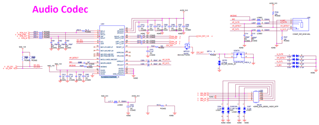
Could you help to review the schematic?

many thanks

Denny

  • Hi Denny,

    Power Supplies

    • Power supply decoupling looks good. Please place the decoupling capacitors as close to the device as possible in the layout.

    • There is a recommended power supply bring-up sequence mentioned in the data sheet. We also have an E2E FAQ on supply sequencing that can be found here.

    Inputs

    • Unused inputs should be connected to GND via a 0.47uF capacitor. To potentially save some board space, all unused inputs can be tied together and connected to GND via a single 0.47uF capacitor.

    Outputs

    • Unused outputs are left floating which is recommended.

    • I see that MIC/headset detection feature is being used. For HP_DETECT, it is pulled up to 3.3V. For headset detection to properly work, this is not needed. I have included an application note on using Headset detection to provide some more information regarding this feature.

    Digital Interface

    • I see that there are some series resistors on the digital interface pins (BLCK, WCLK, DIN, DOUT) with a value of 0ohms. To help with ringing and overshoot, we recommend using a small resistance of 22-33ohms.

    I2C

    • I2C lines are pulled up to IOVDD which is recommended.

    3000.Headset_Detection.pdf

    Regards,

    Aaron Estrada

  • Dear Aaron

    Customer have two questions of  TI/ TLV320AIC3104IRHBT as below.

    Could you give some recommend?

    1. The Pin31 (Reset pin) of TI/ TLV320AIC3104IRHBT. It is pull high or floating in chipset internal.
    2. Must reset pin be pull down for at least 10ns when all power are ready?

    Many thanks

    Denny

  • Hi Denny,

    1. I believe the RESET pin is open drain and should be pulled high and driven low as needed. 

    2. RESET must be held low during the power supply sequence and should continue to stay low at least 10ns after all supplies are fully powered. 

    Regards,

    Aaron Estrada